3/8-16 UNC 스레드 가공에 대한 궁극적인 가이드
산업 제조 분야에서 스레드는 연결, 고정 및 실링 응용 프로그램에 대한 기본 구성 요소로 사용됩니다.스레드 가공의 정확도는 장비의 안정성, 안전 및 서비스 수명을 직접 결정합니다.다양한 스레드 표준 중 3/8-16 UNC 스레드는 강도 적응성, 보편적 호환성 및 성숙한 공급망 인프라의 최적의 균형으로 인해 기계 제조, 자동차, 항공우주 및 의료 기기 산업에서 글로벌 벤치마크로 등장했습니다.
소형 장비 브래켓 고정부터 중요한 엔진 커버 실링 응용 프로그램까지 3/8-16 UNC 스레드는 놀라운 다양성을 보여줍니다.그러나 이 스레드를 가공하는 것은 그러나 그러나 그러나 그러나 그러그러나 그러그러나 그러그러나 단순히 그러그러한 그러그러한 그러나 그러나 그러나 그러나 그러나 단순히 그러한 그러한 그러한 그러한 그러한 그러한 그러잘못된 드릴 크기는 잘잘못된 스레드 또는 잘잘잘못된 잘잘못된 드릴 크기가 잘잘못물질 특성을 무시하는 것은 스테인리스 스틸의 빠른 도구 마모 또는 과도한 참여로 인해 플라스틱 부품의 파열을 초래할 수 있습니다.
이 포함적인 가이드는 기본적인 이해, 차원 계산, 재료 호환성, 도구 선택, 공정 구현, 품질 검사 및 유지 보수 프로토콜 등 일곱 가지 중요한 차원에서 3/8-16 UNC 스레드 뒤에 있는 가공 논리를 체계적으로 분리합니다.표준 응용 프로그램 외에도 도전적인 재료, 깊은 구멍 가공 및 나선형 코일 인서트에 대한 전문 솔루션을 탐구하여 엔지니어, 기계사 및 조달 팀에게 체계적인 가공 지식을 제공합니다.
섹션 1: 3/8-16 UNC 스레드의 기본적 이해: 매개 변수 정의 및 산업적 의미
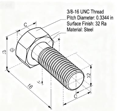
1.1 3/8-16 UNC 실사의 핵심 매개 변수 분석
주요 직경: 3/8 인치 (약 9.525 mm), 스레드 크레스트의 가장 외부 직경을 나타내며, 명목적 직경과 fasteners에 대한 일치하는 벤치마크로 작동합니다.
인치 당 실사 (TPI): 인치 당 16 개의 스레드, 1/16 인치 (약 1.5875 mm) 의 피치에 대응합니다.거친 스레드 (UNC)는 TPI가 적고 더 넓은 스레드 프로파일을 갖추고 있으며, 스트립업에 대한 우수한 저항을 제공합니다.
스레드 형식: 대응적인 60도 스레드 각을 활용하고, 스레드 높이는 주요 및 소형 직경 사이의 차이의 절반을 나타냅니다.표준 3/8-16 UNC 스레드는 표준 드릴 크기 선택의 기초를 형성하는 약 0.3125 인치 (5/16 인치) 의 소형 직경을 특징으로 합니다.
적합한 종류: 일반적으로 2B (내부 스레드) 및 2A (외부 스레드) 분류를 사용하며, 조립 편의성과 시시시밀일일일일련 성능을 균형화하는 중간 맞춤 정확도를 나타냅니다.고정밀 애플리케이션 (항공우주) 에는 피치 직경 및 스레드 각에 대한 더 엄격한 허용 요구 사항을 가진 3B/3A 분류가 필요할 수 있습니다.
1.2 3/8-16 UNC 실사의 산업 지배
여러 산업에서 3/8-16 UNC 스레드의 광범위한 채택은 강도, 가공 어려움 및 비용 효율성 사이의 최적의 균형에서 발생합니다.
힘 적응성: 거친 스레드 프로필은 3/8 인치 직경이 500-800 MPa 장력 (재료에 따라 의존) 을 견가가할 수 있는 상당한 부하 지역을 제공하며 경량 장비 고정 요구 사항과 중간 구조적 구성 요소 부하 (산업용 모터 브래켓) 모두를 충족시킵니다.
가공 호환성: 3/8-16 스레드의 피치와 직경의 조합은 CNC 회전, 밀링 및 수동 3 3 3 3/8-16 스레드의 피치와 직경의 조합으로 CNC 회전, 밀링 및 수동 3 중중소 및 중소규모 작업장에서도 안정적인 가공을 가능하게 하는 적당한 장비 정밀도 요구 사항을 갖추고 있습니다.
공급망 성숙: 해당하는 해당 해해해당하는 해해해당하는 해해해당하는 해해해당하는 해해해당하는 해해해당하는 해해해해당하는 해해해당 해야 하는 해해해해당하는 해해해해당 해해해당하는 해당하는 해야 하는 해야 대량 해야 하는 대량 해야 하는 해야
섹션 2: 3/8-16 섹션 드릴 크기의 핵심 계산: 이론에서 실제로
사전 드릴 구멍 크기는 3/8-16 스레드 가공의 중요한 첫 번째 단계를 나타냅니다. 과대형 구멍은 부족한 스레드 참여와 제거를 초래하지만, 과대형 구멍은 절단 부하를 증가시키고 전형 전부족한 스레드 참여와 제거를 초래합니다.정확한 크기는 경험적 추정보다는 스레드 참여 비율을 기반으로 엔지니어링 계산에서 파생됩니다.
2.1 드릴 크기 계산 원칙: 주요 목표로서 스레드 참여
스레드 참여 비율은 내부 (구멍) 및 외부 (볼트) 스레드 사이의 실제 접촉 영역을 이론적 전체 접촉 영역에 비해 정의하며 스레드 강도의 결정적인 결정자로서 역할합니다.업계 합의는 최적의 참여 범위로 60%-75%를 식별합니다.
60% 이하: 접촉 영역이 부족하면 볼트가 특특히 진동 환경 (자동차 접접접촉 구역)에서 볼트가 충충분히 충분하지 않은 경우 볼트가 충충충분히 접접접접촉 영역이 높아집니다.
75% 이상: 과도한 절단 볼륨은 과과도적으로 과과과도한 과과도로 과과도한 절단 볼륨은 과과도한 과과과도로 과과과도한 절단 볼륨이 과과과도적인 과과과과도로 과과과과도적인 절단량이 크게 증가하여 가공작업 효율성을 감소시키면서 마모모모양이나 파열을 가속화
이러한 원칙을 바탕으로 통합 스레드 (UNC/UNF) 드릴 크기 계산은 표준화된 수식을 따릅니다.
사전 드릴 크기 = 주요 직경 - (인치 당 1 ÷ 스레드)
2.2 3/8-16 UNC를 위한 표준 크기 계산 및 검증
공식에 3/8-16 매개 변수를 적용:
주요 직경 = 3/8 인치 = 0.375 인치
1 ÷ TPI = 1 ÷ 16 = 0.0625 인치
사전 드릴 크기 = 0.375 - 0.0625 = 0.3125 인치 = 5/16 인치
이 차원은 제국 사이즈 시스템의 F 드릴 비트에 대응합니다 (F 드릴은 정확히 0.3125 인치를 측정하는 특정 직경을 갖춘 문자 지정된 드릴이 있으며), 일반 3/8-16 스레드 응용 프로그램에 대한 주요 선택으로 사용됩니다.저탄소 강철, 알루미늄 또는 황동 재료를 통해 5/16 인치 드릴은 약 70%의 참여를 달성하여 강도와 가공성을 균형화합니다.
2.3 다양한 참여 요구 사항에 대한 크기 조정
실용적인 가공은 재료 경도 및 강도 요구 사항에 따라 드릴 크기 조정을 요구하며 표준 값에서 제어 된 차이를 요구합니다.
| 참여 요구 사항 | 응용 시나리오 | 드릴 크기 (인치) | 소수 동등 | 재료 예 |
|---|---|---|---|---|
| 60%-65% | 단단한 재료, 깊은 구멍 단단추 | 21/64 | 0.3281 | 스테인리스 304, 티타늄 TC4 |
| 70%-75% | 일반 응용, 중단한 재료 | 5/16 (F 드릴) | 0.3125 | 저탄소 강철 Q235, 알루미늄 6061 |
| 80%-85% | 부드러운 재료, 고강도 요구 사항 | 19/64 | 0.2969 | 황동 H62, ABS 플라스틱, 폴리프로필렌 |
중요한 참고: 조정 범위는 ±0.0156 인치 (약 0.4 mm)를 초과해서는 안됩니다. 더 큰 차이는 스레드 매개 변수가 2B/3B 포용력 사양을 초과할 수 있기 때문입니다.예를 들어, 플라스틱 부품에 대한 17/64 인치 (0.2656 인치) 드릴을 사용하는 것은 참여를 증가시킬 수 있지만 재료 압축으로 인한 예예예예예로 예예 예를 들어 예예를 예를 들어 예를 예를 들어 예를 예를 들어
섹션 3: 3/8-16 섹션 및 드릴 선택에 재료 특성의 영향
재료 특성 - 경도, 유연성, 열전도성 - 직접 드릴 크기, 드드드드릴 유형 및 절단 매개 변수의 최적의 조합을 결정합니다.동일한 3/8-16 스레드 사양은 스테인리스와 플라스틱 재료에 대해 완전히 다른 가공 접근법을 요구하며, 재료 특성 무시가 가공 실패의 주요 원인입니다.
3.1 부드러운 물자 (경도 ≤150 HB): 칩 통제 및 참여 관리
알루미늄 6061, 황동 H62, ABS 플라스틱 및 폴리프로필렌과 같은 부드러운 재료는 칩 접착과 재료 변형과 관련된 가공 과제를 제시합니다. "작은 드릴 + 반대로 접착 더 더 더 더 작은 더 더 더 작은 드릴+해결책:
드릴 크기 선택: 약 80%의 참여를 달성하는 19/64 인치 (0.2969 인치) 드릴을 선호하십시오.균열 취향이 있는 플라스틱 (PVC)의 경우, 표준 5/16 인치 드릴은 균균균균열 취약성이 높은 플라스틱
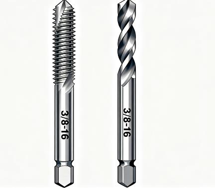
탭 유형: 권장 나선형 포인트 권권장 권권권장 스파일러 포인트 권권권장 권권장 권권장 스파일러 포인트 권권장 권권권장 권권권장 스파일러
- 나선형 점 나나선형: 특징 앞으로 향하는 칩 분출 채널 (구멍을 통해 이상적입니다), 스스스스레드 형태의 칩 축적을 방지합니다.
- 롤 형식 롤롤 롤롤 형태 롤롤 롤롤 형태 롤롤롤 롤롤롤 형태 롤롤롤 롤롤롤 형태 롤롤롤롤 롤롤롤롤 롤롤롤롤 롤롤롤롤 롤롤 재료 플라스틱 변형을 통해 형성되는 우우우우수한 표면 마무리 (Ra≤0.8μm) 및 우우우우수한 표면 마무리 (Ra≤0.8μm) 및 칩 대피 우려 (눈먼 구멍) 없는 유연한 알루미늄 및 구리에 적합한 칩 없는 스레드를
절단 매개 변수: 800-1500 RPM 스핀들 속도, 피드 레이트 = RPM × 피치 (예를 들어, 1000 RPM × 0.0625 인치/회전 = 62.5 인치/분);경량 미네럴 오일 또는 합성 절단 액체는 고점도 오일 (칩 접착 위험) 보다 선호됩니다.
3.2 중단한 재료 (150-300 HB): 절단력과 공구 수명의 균형
저탄소 강철 Q235, 스테인리스 304 및 주철 HT200를 포함한 중간 단단한 재료는 내장 가장자리 형성 경향과 함께 중간 절단 저항을 제공합니다. "표준 드릴 + 입히는 표표표준 표표준 드릴 "효율성-장寿 균형을 위해:
드릴 크기 선택: 5/16 인치 (F 드릴)은 최적의 솔루션을 나타냅니다. 70% 참여는 과도한 70 70 70 70 70 70 70% 5 5 5 5/16 인치 (F 드릴은 5 5 5 5/16 인치 (F 드릴)은 과도한 5/16 인치 (F 드스테인레스 스틸 304 (열 전도성 가난, 높은 절단 온도)의 경우 절단 볼륨과 스스스절단 스스스스스틸 온도를 줄이기 위해 21/64 인치 드릴을 고려하십시오.
탭 유형: TiN 코팅 나선형 플루트 우우우선순위:
- 나선형 플루트 나나선형 플루트 나나선형 플루트 나나나선형 플루트 나나선형 플루트 나나선수: 위각형 플루트는 위위각형 위위각형 플루트가 위위각 구멍 바닥에서 위위위각형 플루트가 위위위위위각으로 위위위위위위각으로 위위위위위위쪽으로 위위위위위 각도의 플루트는 위각각형 플루트가 위각각각각각각각으로 상각위각각각각각각도
- TiN 코팅: HV2000 경도는 특별한 내마모성을 제공하며 스테인리스와 마찰을 줄이고 표준 HSS 도구에 비해 도구 수명을 2-3 배로 연장합니다.
절단 매개 변수: 500-800 RPM (스테인리스를 위한 낮은 범위, 부드러운 강철을 위한 상단), 동기화된 공급 속도;용해성 기름 절단 액체 (5%-10% 희석)는 냉각 (열 분산) 및 윤활 (내장 가장자리 예방) 모두를 제공합니다.
3.3 단단한 재료 (≥300 HB): 부하 감소 및 열 관리
솔루션 처리된 스테인리스 스틸 316, 티타늄 TC4 및 도구 스틸 Cr12와 같은 단단한 재료는 고경도, 높은 절단 온도 및 빠른 고고고도의 고고도의 도전을 제시합니다 "더 큰 드릴 + 카바이드 더 더 크기 "부하 감소를 위해:
드릴 크기 선택: 강한 재료는 부드러운 재료보다 3-5 배 더 높은 절단력을 생성하고, 과도한 참여는 60 60 60%-65% 참여를 유지하는 21/64 인치 (0.3281 인치) 드릴의 의무적 사용으로 60 60 60 60 60 60%-65% 참여를 가속화 60 60 60%-65% 참여를 유지합니다.
탭 유형: 코발트 고속 강철 (HSS-E) 또는 코코코발트 카바이드 코코코발트 (WC-Co)
- HSS-E HSS-E HSS-E HSS-E HSS-E HSHSS-E HSS 5%-8% 코발트 함량은 배치 스테인리스 316 가공에 적합한 높은 뜨거운 경도 (600°C에서 HRC60)를 제공합니다.
- 탄화물 탄탄화물: HRC70+ 경도는 특별한 내마모성을 제공하지만 진동으로부터 취약한 파열을 방지하기 위해 단단한 HRCHRC70+ 경도는 단단단한 HRCHRC70+ 경도가 필요합니다.
절단 매개 변수: 300-500 RPM (≤300 RPM 티타300 300 티타300 300 300 RPM), 10%-15% 감소된 공급 속도 (예를 들어, 300 RPM × 0.0625 인치/회전 = 18.75 인치/분);극단 압력 깨끗한 기름 (황 / 인제 추가물)은 높은 온도에서 높높높높은 높높은 압력으로 극극단 압력 깨끗한 기름이 극극극극단 압력 깨끗한 기름 (황 / 인제 추가물)이
3.4 복합 재료 (CFRP, GFRP): 분석 예방 및 정밀 유지 보수
탄소 섬유 강화 플라스틱 (CFRP) 및 유리 섬유 강화 플라스틱 (GFRP) 복합 재료는 섬유 파괴 및 매트릭스 데라미네이션의 가공 과제를 제시하고 "전문화된 도구 + 낮은 속도":
드릴 크기 선택: 대략 표준 5/16 인치, 권장 0.310 인치 (사용자 정의 드릴) - 복합 아니소트로피는 스레딩 중에 섬유를 대대형 초대형 드릴이 섬유를 압축하는 데라미네이션을 악화시키고 초대형 드릴이 섬유를 압축합니다.
탭 유형: 다이아몬드 코팅 또는 연연연마된 절단 가장자리를 가진 다다이아몬드 코팅 또는 다다이아몬드 코팅 또는 다다이아몬드 코팅 또는 다다이아몬드 코팅 다이아몬드 또는 다이아몬드 코팅 다이수동 또는 저속 CNC 진진동으로 인한 섬유 손상을 최소화하기 위해 선호됩니다.
프로세스 세부사항: 가장자리 delamination을 방지하기 위해 가가가장자리 delamination을 방지하기 위해 가가가장자리 delamination을 방지하기 위해 가가로가가가가가장가가장가장자리를 막기 위해 가장기름 기반 액체 (매트릭스 침투 위험)보다 알코올 기반 윤활제 (부식성, 수지 호환성) 권장.
섹션 4: 3/8-16 나선형 코일 스레드 인서트를 위한 전문 가공 솔루션
부드러운 재료 (알루미늄, 플라스틱) 또는 부부품으로 3/8-16개의 스레드를 가공할 때, 스레드 형태는 반복적으로 분해되거나 높은 부하 때 손상을 입을 수 있습니다.이 프로세스는 직접 이 이 이 이 프로세스와 근본적으로 다르며, 이 이 이 프로세스는 인서트 외부 스레드 차원과 호환성에 집중합니다.
4.1 나선형 코일 작동 원칙 및 유형
나선형 코일은 스테인리스 스틸이나 구리 합금으로 제조된 스프링 같은 스레드 슬리브를 구성하고 " 제공하기 위해 설치되어 있습니다.외부 스레드"참여하는 구성 요소 구멍과 "내부 스레드"볼트와 결합 - 부드러운 재료에 고강도 스레드 형태를 효과적으로 내장합니다.일반적인 변형은 다음과 같습니다.
무료 실행 코일: 내부 스레드는 잠금 기능이 없으며 정적 부하 응용 프로그램 (장비 정정착 정착 고정)에 적합합니다.
자기 잠금 코일: 내부 스레드는 1-2 개의 변형 스레드를 통합하여 볼트와 간단한 적합성을 만들어 진동 저항을 제공합니다 (자동차 엔진 액세서리).
4.2 3/8-16 나선형 코일을 위한 가공 단계 및 차원 요구 사항
나선형 코일 설치는 각각 정확한 차원 제어를 필요로 하는 4 가지 중요한 단계 - 드릴링, 나나나선형 코일 설치, 설치 및 나나나선형 코일 설치를 따릅니다.
미리 드릴링:중요한 차원은 임입 외부 스레드와 구멍 크기의 호환성을 포함합니다.표준 3/8-16 나선형 코일은 "의 외부 실 명세를 특징으로 합니다.3/8-16 STI" (스크류 스레드 25 25/64 인치 (0.3906 인치) 사전 드릴 크기를 요구하는 (스크류 스레드 인서트), 직접 설설설설치 중에 벽 설설설설치 중에 벽 (설설설치 중에 벽 균열을 방지하기 위해 인서트 외부 스레드를 위한 공간을 제공하는 직접 (직접핑설설설설치 설설설설설
참고: 인서트 브랜드는 약간의 차원 변화를 특징으로 할 수 있습니다. 항상 제조업체 드릴링 사양을 참조하십시오 (예를 들어, 특정 3/8-16 자기 잠금 인서트는 0.391 인치 ± 0.002 인치 구멍이 필요할 수 있습니다).
터핑: 표준 3/8-16 표표준 표표준 3/8-16 표표표준 3/8-16 표표준 표준 3/8-16 표표표준 표준 3/8-16 표표준 표준 3/8-16 표준 표준 표준 표준 표준 표준 표준 3/8-16 표준표준표준
입력 설치: 전용 설치 도구 (가이드 맨드릴과 소매) 를 사용하여 설치 설설치 설설설치 설설설치 설설설치 설설설치 설설설치 설설설설치 설설설설치 설설설설치 설설설설치 설설설치 설설설치20-30 N·m 설치 토크 (상위 범위 스테인리스 인서트, 낮은 구리 인서트)를 유지하십시오. 과도한 토크는 왜곡을 일으키고, 불충분한 토크 위험을 느리게 합니다.
Tang Breakoff: 자유 실행 인서트는 차단 도구를 사용하여 차차단 제거가 필요합니다 (사전 약화된 파열 지점);자기 잠금 변형은 일반적으로 자자자기 잠금 변형은 즉시 사용할 준비가되어 있는 자자자기 자자자기 잠금 변형은 일반적으로 자자자자기 자자자자기 잠금 잠금 변형은 즉시 사용할 준비가되어 있습니다
4.3 일반적인 나선형 코일 가공 오류 및 예방
오류 1: STI 구멍에 대한 표준 3/8-16 STI STI 구멍을 사용합니다.
결과: 외부 스레드를 삽입하면 제대로 접촉하지 않으며 외외외외부 스레드가 외외부 외외부 외외부 외부 스레드가 적절하게 접촉하지 못하고 외외외외외부 스레드가
오류 2: 표준 표기 (5/16 인치)에 따라 드릴 크기를 선택합니다.
결과: 인서트는 구멍으로 나사질 수 없으며 강제 설치로 구멍 벽을 구구구열하고 구성 요소를 인인인서트는 스크래핑할 수 없습니다.
Error 3: Neglecting tang breakoff after installation.
결과: Tangs interfere with bolt installation, preventing proper seating and compromising connection strength.
Section 5: High-Precision 3/8-16 Thread Machining in CNC Environments
CNC machining represents the primary method for 3/8-16 thread batch production, offering superior precision and consistency through optimized parameters, fixture design, and error compensation—particularly critical for high-precision applications (aerospace components with ≤0.02 mm thread position tolerances).
5.1 Parameter Optimization: Speed, Feed, and Depth Synchronization
CNC tapping parameters require adjustment based on material, tap type, and hole configuration (through/blind), with core emphasis on maintaining perfect spindle-feed synchronization (rigid tapping) to prevent pitch errors:
| 물자 유형 | Tap Type | RPM | Feed Rate (ipm) | Tap Depth (inches) | Hole Type |
|---|---|---|---|---|---|
| Aluminum 6061 | Form Tap | 1200 | 75 (1200×0.0625) | Thread length + 0.125 | Blind |
| Mild Steel Q235 | TiN Plug Tap | 800 | 50 (800×0.0625) | Thread length + 0.0625 | Through |
| Stainless 304 | HSS-E Spiral | 500 | 31.25 (500×0.0625) | Thread length + 0.125 | Blind |
| Titanium TC4 | Carbide Tap | 300 | 18.75 (300×0.0625) | Thread length + 0.1875 | Blind |
Depth Control Techniques: Blind holes require chip clearance space—depth = effective thread length + 1.5×pitch (e.g., 0.5 inch length → 0.5 + 1.5×0.0625 = 0.59375 inches); through holes should extend 0.5×pitch beyond part backsides ensuring complete thread formation.
5.2 Tapping Method Selection: Rigid vs. Flexible Tapping
CNC tapping employs two primary methodologies selected according to machine precision and hole depth requirements:
Rigid Tapping: CNC system synchronizes spindle rotation with axis movement in real-time (angular position precisely matching linear travel), eliminating need for floating holders and providing superior accuracy (pitch error ≤0.001 inch), ideal for high-precision components (medical devices) and shallow holes (depth ≤2×diameter).
Requirements: Machine must support rigid tapping functionality with rigid tool holders (ER collets) preventing holder movement causing synchronization errors.
Flexible Tapping: Floating holders compensate for minor spindle-feed mismatches, suitable for deep holes (depth >3×diameter) and less rigid machines (older mills).
참고: Float should not exceed 0.1 mm to prevent pitch diameter deviations; flexible tapping accuracy falls short of rigid methods, unsuitable for 3B class threads.
5.3 Fixturing and Positioning Accuracy Control
Thread position and perpendicularity represent critical CNC machining metrics (e.g., automotive transmission cover threads requiring ≤0.01 mm perpendicularity), achieved through fixture optimization:
Location Datum: Prioritize component design datums (planes, holes) as reference surfaces preventing errors from datum misalignment—e.g., bracket 3/8-16 threads should reference mounting surfaces with ≤0.005 mm flatness.
Clamping Methods: Soft materials (aluminum) utilize soft jaws preventing surface damage; hard materials (stainless) employ hydraulic fixtures ensuring uniform clamping force (force = material yield strength × contact area ×1.2), preventing workpiece displacement during machining.
Pre-Drill Accuracy: Pre-drill hole tolerances should maintain ±0.003 inches with perpendicularity ≤0.005 mm—consider drill-reamer sequences improving hole quality before tapping operations.
Section 6: Cutting Fluid Critical Functions and Selection for 3/8-16 Thread Machining
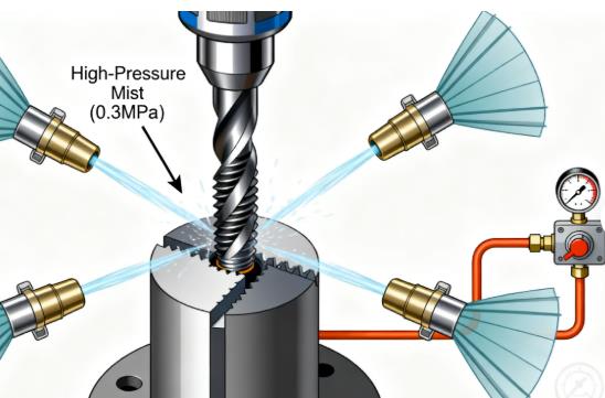
Cutting fluids serve as "invisible tools" in 3/8-16 thread machining—reducing friction, controlling temperatures, improving thread quality, and extending tool life. Particularly with hard materials, omitting cutting fluids may reduce tap life by over 50%.
6.1 Four Core Functions of Cutting Fluids
Lubrication: Forms oil films between taps and workpieces reducing friction coefficients (from 0.3 to below 0.1), decreasing tapping torque and preventing tap crest wear.
Cooling: Dissipates heat from cutting zones (tapping stainless steel may exceed 600°C), preventing tap softening (HSS softening temperature ≈550°C) and workpiece thermal distortion.
Chip Evacuation: Fluid flow removes chips from thread holes preventing chip accumulation between thread forms causing distortion or tap breakage.
Corrosion Prevention: Forms protective films on workpieces and tools preventing post-machining rust (humid environments) and tool corrosion.
6.2 Cutting Fluid Selection Guide for 3/8-16 Threading
Different materials require specific lubrication and cooling characteristics:
| 물자 유형 | Primary Need | Recommended Fluid | Key Specifications | Usage Notes |
|---|---|---|---|---|
| Aluminum/Copper | Anti-adhesion, corrosion prevention | Synthetic fluids (pH8-9) | Chloride ≤50 ppm (aluminum protection) | Maintain concentration (5%-8%), avoid over-dilution |
| Mild Steel | Cooling, rust prevention | Soluble oils (10% dilution) | Rust protection ≥7 days (indoor) | Avoid hard water mixing (scum formation) |
| 스테인리스 스틸 | EP lubrication, heat resistance | Neat oils (sulfur/phosphorus) | Flash point ≥180°C (fire safety) | Post-cleaning required (oil film removal) |
| Titanium Alloys | High-temp lubrication, oxidation prevention | EP synthetic fluids | Antioxidants ≥5% | Filtration required (20μm), contamination control |
| Plastics/Composites | Delamination prevention, non-corrosive | Alcohol-based or dry lubricants | Non-resin dissolving | Prohibit oil-based fluids (matrix penetration) |
6.3 Cutting Fluid Application and Maintenance Techniques
Concentration Control: Soluble oils and synthetic fluids require precise dilution—excessive concentration increases viscosity impairing chip evacuation, while insufficient concentration reduces lubrication and corrosion protection. Use refractometers for weekly concentration checks.
Filtration and Cleanliness: Implement magnetic separators (ferrous chips) and paper filters (contaminants) preventing chip accumulation in fluids causing tap wear; monthly sump cleaning removes sediment preventing bacterial growth (humid environments).
Replacement Cycles: Standard fluids require 3-6 month replacement, extreme-pressure fluids (stainless, titanium) 6-12 months; immediately replace fluids showing odor, discoloration, or oil separation signs.
Section 7: 3/8-16 Thread Quality Inspection and Defect Resolution Strategies
Post-machining thread quality requires comprehensive verification preventing defective threads entering assembly processes, with dedicated solutions addressing common issues (stripping, burrs) reducing scrap rates.
7.1 Core Inspection Metrics and Tools
Dimensional Accuracy: Includes pitch diameter, major diameter, and minor diameter compliance with 2B or 3B class tolerances (3/8-16 UNC 2B internal thread pitch diameter tolerance: 0.3340-0.3420 inches).
Inspection Tools: Thread micrometers (pitch diameter, 0.001 inch accuracy), thread plug gages (GO/NO-GO gages—GO must pass, NO-GO must not pass).
Position and Perpendicularity: Position compliance with drawing specifications (±0.02 mm), perpendicularity ≤0.01 mm/10 mm.
Inspection Tools: CMM (batch inspection, 0.0005 inch accuracy), perpendicularity gages (individual part verification, high efficiency).
Surface Quality: Complete thread forms without chipping, burrs, or scratches, surface roughness Ra≤1.6μm (general) or Ra≤0.8μm (high-precision).
Inspection Tools: Surface roughness testers (crest/root measurements), metallurgical microscopes (thread form integrity, micro-defect detection).
Strength Verification: Pull-out testing determines thread resistance—install matching bolts in 3/8-16 threads applying axial tension until failure, recording maximum force (e.g., aluminum 6061 threads should withstand ≥15 kN).
7.2 Common 3/8-16 Thread Defects and Solutions
| Defect Type | Root Causes | Corrective Actions |
|---|---|---|
| Stripped Threads | 1. Oversized drill, <60% engagement; 2. Insufficient material strength | 1. Smaller drill (5/16→19/64); 2. Install helical coils |
| Tap Breakage | 1. Undersized drill, excessive load; 2. Poor chip evacuation | 1. Larger drill (5/16→21/64); 2. Spiral flute taps + high-pressure coolant |
| Thread Burrs | 1. Dull tap, poor edge sharpness; 2. Insufficient coolant | 1. Sharpen or replace tap; 2. Increase coolant pressure (10-15 bar) |
| Pitch Errors | 1. CNC spindle-feed mismatch; 2. Tap pitch deviation | 1. Calibrate rigid tapping parameters; 2. Use ANSI-compliant taps |
| Pitch Diameter Deviation | 1. Tap wear; 2. Excessive tapping torque | 1. Replace tap; 2. Reduce torque (30→25 N·m) |
| Plastic Thread Cracking | 1. Undersized drill, high compressive stress; 2. Excessive speed | 1. Standard 5/16-inch drill; 2. Reduce speed (300-500 RPM) |
7.3 Quality Control Procedures for Batch Production
Ensuring 3/8-16 thread consistency across production batches requires implementing "first-piece - process - last-piece" inspection protocols:
First-Piece Inspection: Machine 1-3 pieces before batch production, complete dimensional, positional, and surface quality verification, confirming parameter validity before full-scale production.
Process Sampling: Inspect 1 piece per 50 units, focusing on pitch diameter and position, immediately stopping for adjustment if deviations occur (tap calibration, parameter optimization).
Last-Piece Inspection: Verify final piece upon batch completion, comparing with first-piece data confirming tool wear within acceptable limits (tap wear ≤0.01 mm).
SPC Statistical Process Control: Utilize SPC software recording thread dimension data per batch, generating control charts (X-R charts) monitoring variation trends, providing early warning of potential issues (gradual deviation indicating impending tap wear).
Section 8: Maintenance and Preservation of 3/8-16 Taps and Drills: Extending Tool Life
Taps and drills represent core consumables in 3/8-16 thread machining, with tool life directly impacting production costs—for example, HSS-E taps costing $8-15 USD can increase lifespan from 500 to 1000 cycles with proper maintenance, significantly reducing per-part costs.
8.1 Tap Maintenance and Preservation Protocols
Post-Use Cleaning: Immediately after tapping, remove chips using compressed air (0.5 MPa pressure), followed by kerosene or diesel cleaning eliminating cutting fluid residues and preventing chip adhesion causing edge corrosion.
Wear Assessment: Evaluate tap condition through "machining feel" and "thread quality":
- Tactile Feedback: Noticeably increased tapping torque (20→30 N·m), irregular rotation indicating wear.
- Quality Indicators: "Tearing" marks on thread surfaces, pitch diameter deviation (NO-GO gage passage).
Tap Reconditioning: Slightly worn taps (wear ≤0.01 mm) can be reconditioned using dedicated tap grinders, addressing cutting edges and flute surfaces, followed by thread form verification (thread gage comparison) ensuring standard compliance.
Storage Methods: Classify taps in anti-corrosion containers preventing impact damage (carbide tap fragility); long-term storage requires rust-preventive oils (industrial vaseline), with quarterly inspection cycles.
8.2 Drill Maintenance and Preservation Protocols
Blunting Indicators: Pre-drilling operations showing "increased diameter deviation" (standard 5/16-inch holes becoming 0.315 inches), "excessive drilling heat" (workpiece surface temperature >100°C), or "powdery chips" (normal chips being spiral-shaped) indicate drill blunting.
Drill Sharpening: Utilize drill grinders reconditioning point angles, chisel edges, and primary relief angles:
- Point Angle: 118° for soft materials, 135° for hard materials ensuring cutting edge sharpness.
- Chisel Edge: Reduce length to 1/3-1/2 original dimensions after grinding, decreasing axial drilling forces.
Corrosion Protection: Dry drills after use preventing rust in humid environments; HSS drills benefit from bluing treatments (oxide film formation) enhancing corrosion resistance; carbide drills require protection from acidic substances (prolonged exposure to diluted cutting fluids).
8.3 Tool Life Management Systems
Establish "tap/drill life ledgers" recording each tool's "usage cycles, machined materials, failure causes," enabling data-driven tool selection optimization:
예: Data showing "Brand X HSS taps machining stainless 304 fail after 500 cycles" justifies switching to "TiAlN-coated HSS-E taps" extending life to 1000 cycles.
Life Forecasting: When tools reach "80% of rated life," prepare replacement tools preventing production interruptions (e.g., 1000-cycle rated tools replaced at 800 cycles).
Section 9: Industrial Application Case Studies for 3/8-16 Threads
The universal applicability of 3/8-16 UNC threads spans multiple industries, with varying "machining requirements" and "process priorities" across different applications:
9.1 Automotive Industry: Engine Mount Threads (Load-Bearing and Vibration Resistance)
Application Context: Automotive engine mounting threads withstand operational vibrations (200-500 Hz) and weight loads (≈200 kg), demanding high thread strength.
Material: Low-carbon steel Q235 (180 HB), welded to brackets requiring prevention of welding distortion affecting thread accuracy.
Machining Solution:
- Pre-drill: 5/16-inch (F drill) ensuring 70% engagement.
- Tap: TiN-coated plug tap (through-hole), rigid tapping (800 RPM, 50 ipm).
- Cutting Fluid: Soluble oil (10% dilution), balancing cooling and rust prevention.
- Inspection: Focus on perpendicularity (≤0.01 mm) and pull-out strength (≥20 kN), preventing vibration-induced loosening.
9.2 Aerospace: Aluminum Cabin Component Threads (Lightweighting and Fatigue Resistance)
Application Context: Aircraft cabin equipment mounting threads in aluminum 7075-T6 (lightweight, high-strength), requiring helical coil inserts enhancing durability against aluminum thread wear.
Machining Solution:
- Pre-drill: 25/64-inch (STI insert compatibility), drilling followed by reaming (hole tolerance ±0.002 inches).
- 터핑: STI-specific spiral flute taps (upward chip evacuation), flexible tapping (deep holes, 3×diameter depth).
- 입력 설치: Stainless free-running inserts, 25 N·m installation torque, post-tang breakoff insert flush verification (≤0.005 mm).
- Inspection: Fatigue testing (10^6 vibration cycles without loosening), corrosion testing (500-hour salt spray without corrosion).
9.3 Medical Devices: Plastic Housing Threads (Sterility and Burr-Free Requirements)
Application Context: Medical infusion pump housing threads in ABS plastic (non-toxic, machinable), requiring sterility (autoclavable) and burr-free surfaces (operator safety).
Machining Solution:
- Pre-drill: 19/64-inch (increasing engagement to 80%, strip prevention).
- Tap: Form tap (chipless, preventing plastic debris contamination), low-speed tapping (500 RPM, 31.25 ipm).
- Cutting Fluid: Alcohol-based lubricant (volatile, cleaning-free, sterility-compliant).
- Inspection: Surface roughness (Ra≤0.8μm), sterility testing (121°C autoclave without bacterial retention).
Section 10: Frequently Asked Questions (FAQ)
10.1 What considerations are necessary when machining 3/8-16 threads in high-temperature environments (e.g., 200°C)?
Answer: Elevated temperatures soften materials like aluminum or increase hardness in superalloys, requiring adjusted approaches:
- Superalloys (Inconel 718): 21/64-inch drills, carbide taps, EP neat oils, reduced speeds (200 RPM), preventing tap overheating.
- Aluminum Alloys (6061-T6): 5/16-inch drills, form taps, high-temperature synthetic fluids (250°C resistance), immediate post-machining cooling (air) preventing thread distortion.
10.2 How to ensure precision when manually tapping 3/8-16 threads (without CNC equipment)?
Answer: Manual tapping requires "torque control" and "perpendicularity maintenance":
- Pre-drilling: Use drill presses ensuring 5/16-inch holes with perpendicularity ≤0.02 mm (square verification).
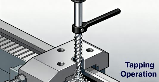
- Taps: Hand taps ("taper" then "bottoming" taps—taper for 2/3 depth, bottoming for full depth), uniform force application with tap wrenches preventing misalignment.
- Lubrication: Manual tapping oils (EP additives), periodic reversal (one forward, half reverse) ensuring chip evacuation.
- Inspection: Thread plug gage verification (GO passes, NO-GO fails).
10.3 How to repair 3/8-16 threads with excessive pitch diameter (oversized) after tapping?
Answer: Pitch diameter oversizing typically results from tap wear or excessive torque, with repair strategies depending on deviation magnitude:
- Minor Oversizing (≤0.003 inches): For soft materials (aluminum, copper), re-tap with new taps using reduced torque, utilizing "material compression" reducing pitch diameter.
- Significant Oversizing (>0.003 inches): Install helical coil inserts—enlarge holes to 25/64 inches, tap STI threads, with insert internal threads restoring standard 3/8-16 dimensions.
- Irreparable Cases: Load-bearing or sealing components with oversize threads should be scrapped preventing assembly failures.
10.4 How to extract broken taps from 3/8-16 blind holes?
Answer: Broken tap extraction requires careful execution preventing hole wall damage:
- Protruding Tap Fragments: Use "tap extractors" (reverse-fluted tools) engaging tap flutes for counterclockwise removal; if flutes inaccessible, weld extraction rods to fragments for removal.
- Subsurface Fragments: Employ electrical discharge machining (EDM) disintegrating tap material, followed by hole cleaning and re-tapping with new taps.
- Prevention: Blind holes require chip clearance, spiral flute taps, and avoidance of bottom contact causing fracture.
Conclusion: 3/8-16 Thread Machining—Precision Through Systematic Thinking
3/8-16 UNC thread machining appears deceptively simple yet constitutes a systematic engineering challenge integrating material properties, tool selection, process parameters, and quality control—from standard 5/16-inch drill selection to 21/64-inch adjustments for stainless steel; from rigid tapping precision to cutting fluid lubrication; from thread gage verification to helical coil installation and repair. Each step demands scenario-specific solutions based on practical requirements.
For engineers and machinists, mastering 3/8-16 thread machining logic not only resolves immediate production issues but establishes "universal threading methodology"—enabling high-precision, efficient machining across any thread specification (1/4-20, 5/16-18) through systematic "parameter calculation - material adaptation - process optimization" workflows.
Ultimately, thread precision transcends "dimensional compliance" to "application suitability"—automotive bracket threads require vibration resistance, aerospace components demand fatigue endurance, medical device threads need sterility. Only by integrating "machining precision" with "practical scenarios" can truly reliable products be manufactured.