Drill Size Chart: Fractional, Metric, Number, Letter & Tap Sizes
Choosing the correct drill size is essential for producing accurate holes, creating reliable threads, and avoiding unnecessary machining problems. However, drill bits are specified using several different systems, including fractional inches, metric diameters, number gauges, and letter sizes.
A drill size chart makes it easier to compare these systems and find the closest equivalent drill diameter for machining, fabrication, assembly, or tapping.
This guide covers the most common drill bit sizes used in CNC machining and includes fractional-to-decimal conversions, number and letter drill sizes, and common tap drill sizes.
Understanding Drill Bit Size Systems
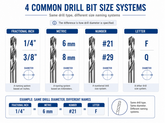
Drill sizes are commonly specified using four systems: fractional inch, metric, number, and letter sizes. Manufacturers such as ICS Cutting Tools publish conversion charts that place these systems together using decimal-inch and millimeter equivalents.
Fractional drill sizes are widely used in inch-based manufacturing and are typically expressed in fractions such as 1/8", 1/4", or 3/8".
Metric drill sizes are specified directly in millimeters, such as 3 mm, 6.5 mm, or 10 mm.
Number drill sizes use numbers such as #80 through #1. Unlike a simple numerical diameter system, smaller gauge numbers generally represent larger drill diameters.
Letter drill sizes run from A to Z and cover sizes between many common fractional drill diameters. Letter drills are particularly useful when an exact fractional drill does not provide the required hole size.
Because CNC drawings and fastener specifications may use different systems, decimal-inch and metric equivalents are useful when selecting available tooling.
Fractional Drill Size Chart
The table below shows commonly used fractional drill sizes and their decimal and metric equivalents. The conversions agree with published cutting-tool drill conversion data.
Fractional Size | Decimal Inch | Metric |
1/64" | 0.0156" | 0.397 mm |
1/32" | 0.0313" | 0.794 mm |
3/64" | 0.0469" | 1.191 mm |
1/16" | 0.0625" | 1.588 mm |
5/64" | 0.0781" | 1.984 mm |
3/32" | 0.0938" | 2.381 mm |
7/64" | 0.1094" | 2.778 mm |
1/8" | 0.1250" | 3.175 mm |
9/64" | 0.1406" | 3.572 mm |
5/32" | 0.1563" | 3.969 mm |
11/64" | 0.1719" | 4.366 mm |
3/16" | 0.1875" | 4.763 mm |
13/64" | 0.2031" | 5.159 mm |
7/32" | 0.2188" | 5.556 mm |
15/64" | 0.2344" | 5.953 mm |
1/4" | 0.2500" | 6.350 mm |
17/64" | 0.2656" | 6.747 mm |
9/32" | 0.2813" | 7.144 mm |
19/64" | 0.2969" | 7.541 mm |
5/16" | 0.3125" | 7.938 mm |
21/64" | 0.3281" | 8.334 mm |
11/32" | 0.3438" | 8.731 mm |
23/64" | 0.3594" | 9.128 mm |
3/8" | 0.3750" | 9.525 mm |
25/64" | 0.3906" | 9.922 mm |
13/32" | 0.4063" | 10.319 mm |
27/64" | 0.4219" | 10.716 mm |
7/16" | 0.4375" | 11.113 mm |
29/64" | 0.4531" | 11.509 mm |
15/32" | 0.4688" | 11.906 mm |
31/64" | 0.4844" | 12.303 mm |
1/2" | 0.5000" | 12.700 mm |
For CNC machining, the nominal drill diameter is not always the same as the finished-hole diameter. Tool runout, drill geometry, material behavior, machine rigidity, and subsequent operations such as reaming can all affect the final result.
Common Number and Letter Drill Sizes
Number and letter drills provide intermediate sizes that are not always available in standard fractional sets. Their decimal equivalents are standardized references used when selecting drills for tapping and precision hole preparation.
Drill Size | Decimal Inch | Metric |
#60 | 0.0400" | 1.016 mm |
#50 | 0.0700" | 1.778 mm |
#43 | 0.0890" | 2.261 mm |
#36 | 0.1065" | 2.705 mm |
#29 | 0.1360" | 3.454 mm |
#21 | 0.1590" | 4.039 mm |
#7 | 0.2010" | 5.105 mm |
A | 0.2340" | 5.944 mm |
F | 0.2570" | 6.528 mm |
I | 0.2720" | 6.909 mm |
Q | 0.3320" | 8.433 mm |
U | 0.3680" | 9.347 mm |
Z | 0.4130" | 10.490 mm |
These sizes are particularly common in threaded-hole machining because they allow the pre-drilled hole diameter to be matched more closely to the required thread geometry.
Tap Drill Size Chart for Common Inch Threads
A tap drill size is the diameter of the hole drilled before an internal thread is cut with a tap.
The hole must be smaller than the thread's major diameter so that enough material remains for the tap to form the thread profile. However, making the hole unnecessarily small increases tapping torque and can shorten tap life.
Guhring notes that traditional charts often target approximately 75% thread, while lower thread engagement may improve tap life in many applications; the actual recommendation therefore depends on the tap, material, thread class, and machining conditions.
Thread Size | Common Tap Drill | Decimal Size |
#4-40 | #43 | 0.0890" |
#6-32 | #36 | 0.1065" |
#8-32 | #29 | 0.1360" |
#10-24 | #25 | 0.1495" |
#10-32 UNF | #21 | 0.1590" |
1/4-20 UNC | #7 | 0.2010" |
1/4-28 UNF | #3 | 0.2130" |
5/16-18 UNC | F | 0.2570" |
5/16-24 UNF | I | 0.2720" |
3/8-16 UNC | 5/16" | 0.3125" |
3/8-24 UNF | Q | 0.3320" |
7/16-14 UNC | U | 0.3680" |
7/16-20 UNF | 25/64" | 0.3906" |
1/2-13 UNC | 27/64" | 0.4219" |
1/2-20 UNF | 29/64" | 0.4531" |
These values should be treated as common starting points rather than universal production settings. Cutting taps and forming taps require different pre-hole diameters, and tool manufacturers may specify a recommended diameter range for a particular tap. For example, Guhring publishes tap-drill ranges rather than relying on one universal size for every application.
What Is the 10-32 Tap Drill Size?
For a conventional 10-32 UNF cutting tap, a #21 drill is a common tap drill choice.
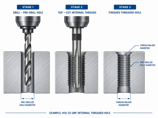
A #21 drill measures:
0.1590 inch, or approximately 4.04 mm.
This is also why simply selecting the nearest fractional drill is not always ideal. For example, a 5/32" drill measures 0.15625", making it slightly smaller than a #21 drill. The smaller hole increases thread engagement and can also increase tapping torque.
For production parts, the final drill diameter should therefore be selected according to the tap manufacturer's recommendation, workpiece material, required thread class, and desired percentage of thread. Guhring's published ranges for 10-32 cutting taps illustrate that acceptable pre-hole diameters can vary with the tool design.
Common Metric Tap Drill Sizes
A useful starting approximation for ISO metric cutting threads is:
Tap Drill Diameter ≈ Thread Major Diameter − Thread Pitch
This produces commonly used starting sizes such as:
Metric Thread | Common Tap Drill |
M3 × 0.5 | 2.5 mm |
M4 × 0.7 | 3.3 mm |
M5 × 0.8 | 4.2 mm |
M6 × 1.0 | 5.0 mm |
M8 × 1.25 | 6.8 mm |
M10 × 1.5 | 8.5 mm |
M10 × 1.25 | 8.8 mm |
M10 × 1.0 | 9.0 mm |
As with inch threads, these are reference values for cutting taps. Form taps require a larger pre-hole because the thread is produced by material displacement rather than chip removal. Tool-specific recommendations should take priority in production machining. Guhring provides a separate drill-size calculator and guidance specifically for thread-forming taps.
Tap Drill Size vs. Clearance Hole Size
A tap drill and a clearance drill serve different purposes.
A tap drill prepares a hole that will subsequently receive an internal thread. A clearance hole, by contrast, allows a bolt or screw to pass through the part without engaging the material.
This distinction is important on engineering drawings. Using a clearance-hole diameter where a tapped hole is required may leave insufficient material to produce the specified thread, while using a tap-drill diameter for a through-bolt hole can make assembly impossible.
Choosing Drill Sizes for CNC Machined Parts
Selecting the nearest drill from a chart is only part of the design process. For CNC-machined components, engineers should also consider:
<!--[if !supportLists]-->· <!--[endif]-->required hole tolerance and surface finish;
<!--[if !supportLists]-->· <!--[endif]-->hole depth and diameter-to-depth ratio;
<!--[if !supportLists]-->· <!--[endif]-->blind-hole bottom clearance;
<!--[if !supportLists]-->· <!--[endif]-->thread type and thread engagement;
<!--[if !supportLists]-->· <!--[endif]-->cutting tap versus forming tap;
<!--[if !supportLists]-->· <!--[endif]-->workpiece material;
<!--[if !supportLists]-->· <!--[endif]-->whether drilling will be followed by boring or reaming.
Where possible, specifying standard drill diameters can simplify tooling and machining. Tight-tolerance holes may require additional operations such as reaming or boring rather than relying on drilling alone.

For custom CNC parts, Rapid-Model can manufacture drilled and threaded features in metals and engineering plastics for prototypes and low-volume production. Providing the CAD model together with thread specifications, tolerances, and critical hole dimensions helps the manufacturing team select an appropriate machining process and inspection method.
Conclusion
A drill size chart provides a practical reference for converting between fractional, metric, number, and letter drill sizes and for selecting starting hole diameters before tapping.
For general machining, the chart can quickly identify the closest available tool. For threaded or precision holes, however, drill diameter should also account for thread engagement, workpiece material, tolerance requirements, and the cutting tool manufacturer's recommendations.
In particular, a #21 drill at 0.1590" (4.04 mm) is a common starting size for a 10-32 UNF cutting tap, while production applications may use a slightly different diameter depending on the tap and required thread engagement.