Bevel vs Chamfer vs Taper: What's the Difference in Machining?
Quick answer: A chamfer is a localized flat, angled edge break. A bevel is an angled edge or surface, often larger and commonly used in fabrication and welding preparation, although CAD tools may use the terms loosely. A taper is a gradual change in width, thickness, or diameter along a component’s length. A miter is an angled cut or joint used to connect two components. A fillet is a rounded radius transition. The correct choice depends on geometry, function, and manufacturing process.
When designing a mechanical component, small differences in geometry can have a significant impact on manufacturing, assembly, and dimensional accuracy. A beveled edge, a chamfered corner, and a tapered shaft may all appear to have angled surfaces, but they are not necessarily the same feature.
This distinction matters when creating CAD models, interpreting engineering drawings, and selecting CNC machining processes. For example, should you specify a chamfer or a taper on a shaft? Is a bevel the same as a chamfer? Does a miter cut create a bevel? And when should you choose a fillet instead of an angled edge?
Confusing these features can lead to incorrect dimensions, unnecessary machining operations, poor component alignment, and manufacturing misunderstandings. This guide explains the differences between bevel, chamfer, taper, miter, and fillet from a mechanical design and CNC manufacturing perspective.
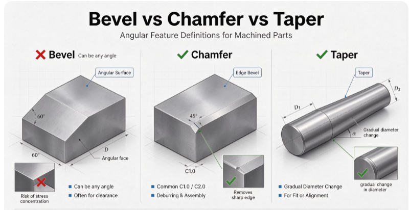
1. What Is a Bevel?
A bevel is an angled surface created by cutting or shaping the edge of a material so that the resulting face is not perpendicular to the adjacent main surface. Unlike a rounded fillet, a bevel creates an angled, non-curved surface. The distinction from a chamfer is one of scale, application, and terminology, covered later in this article.
Bevels are commonly found in metal fabrication, welding, woodworking, glass manufacturing, and mechanical component design.
Common Applications of Bevels
Welding preparation. One of the most important applications of bevels is preparing thick metal components for welding. When two thick steel plates need to be joined, their edges may be cut at an angle to create a groove that allows sufficient weld access and penetration. Common welding preparations include single-bevel groove, double-bevel groove, single-V groove, double-V groove, and beveled butt joints. The exact geometry depends on material thickness, joint design, welding process, and required weld quality.
Mechanical component manufacturing. Beveled edges can also be used in machined components to create angled transitions, provide clearance, or achieve specific functional geometry. Typical applications include precision metal housings, aluminum structural components, industrial machinery parts, metal panels and plates, and components requiring angled mating surfaces.
Edge design and finishing. A bevel can create a visually distinctive edge while removing the sharp original corner. Whether the feature is technically called a bevel or a chamfer depends on the design convention being used.
How Is a Bevel Specified?
A bevel is generally defined by its angle and dimensions. Common examples include a 30° bevel, a 45° bevel, and a 60° bevel.
For welding applications, additional information may be required: bevel angle, bevel depth, root face (land), root opening, and included groove angle.
Expert insight: When a bevel is part of a welding joint, never specify only the angle. The depth of preparation and root-face dimensions can influence weld accessibility, penetration, and the resulting joint geometry. Use the applicable weld-joint drawing symbols and welding procedure.
2. What Is a Chamfer?
A chamfer is a flat, angled surface created by removing material from the sharp intersection of two surfaces. It is commonly used in precision engineering and CNC machining to remove sharp edges, simplify assembly, and improve component handling. The most familiar example is a 45-degree chamfer around the edge of a machined metal component.
Common Applications of Chamfers
Removing sharp edges. Machined metal parts can have sharp edges and burrs after milling, drilling, turning, or cutting. A chamfer provides a controlled edge break that makes a component safer to handle. However, chamfering and deburring are not identical: deburring removes unwanted material, while a specified chamfer produces a defined geometric feature.
Improving assembly. Chamfers are frequently used to guide components into position. Examples include chamfers on shaft ends to facilitate insertion into bores, chamfers around threaded holes to assist fastener entry, chamfers on mating components to reduce edge interference, and chamfers on locating features to simplify alignment.
Improving manufacturing and finishing. Chamfers can often be produced using standard CNC machining tools and relatively simple toolpaths. Common methods include chamfer milling, countersinking, CNC turning, and manual deburring and edge finishing. For simple external edge treatments, chamfers are often economical and easy to reproduce consistently.
Common Chamfer Dimensions
Chamfers are usually specified using a distance and an angle. The exact drawing convention determines how the distance is measured; for critical features, make the dimensioning method unambiguous.
| Chamfer specification | Meaning |
|---|---|
| 1 × 45° | Nominal 1 mm chamfer at 45° |
| 2 × 45° | Nominal 2 mm chamfer at 45° |
| 1 × 30° | Nominal 1 mm chamfer at 30° |
| 0.5 × 45° | Small edge chamfer at 45° |
Expert insight: Do not assume that every sharp edge needs a large chamfer. On a precision locating surface, an oversized chamfer can reduce the usable contact area and interfere with component positioning.
3. What Is a Taper?
A taper is a gradual change in the width, thickness, or diameter of a component along a specified length. Unlike a chamfer, which usually affects a localized edge, a taper extends along a functional portion of the component. In CNC machining, tapers are particularly important for shafts, pins, toolholders, bearings, mechanical fittings, and components requiring precise alignment.
Common Types of Tapers
External taper. Gradually reduces the outside diameter of a cylindrical component. Typical applications include tapered shafts, tapered locating pins, machine toolholders, spindles, and mechanical connecting components.
Internal taper. Gradually changes the diameter of a bore. Examples include tapered sockets, toolholder receivers, precision mechanical fittings, and specialized connecting interfaces.
Linear taper. Has a constant rate of dimensional change along its length; its angled sides form a straight profile in an axial cross-section. This is one of the most common taper geometries in mechanical manufacturing.
Nonlinear taper. Some components use curved or variable-rate taper geometries instead of a constant angular transition. Such profiles may be designed for fluid flow, aerodynamic behavior, weight optimization, or specialized mechanical performance.
What Is a Taper Ratio?
Taper can be specified using an angle or a taper ratio. For a conical taper, the conventional taper ratio is:
T = (D − d) / L
Where:
- T = taper ratio.
- D = larger diameter.
- d = smaller diameter.
- L = axial length of the tapered section.
For example, consider a shaft with a larger diameter of 20 mm, a smaller diameter of 16 mm, and a taper length of 100 mm:
T = (20 − 16) / 100 = 4 / 100
Therefore, taper ratio = 1:25. This means the diameter decreases by 1 mm for every 25 mm of axial length.
How Do You Calculate the Taper Angle?
For a symmetrical conical taper, the half-angle is:
θ = arctan[(D − d) / (2L)]
The included angle is:
α = 2 · arctan[(D − d) / (2L)]
Using the previous example:
θ = arctan(4 / 200) ≈ 1.146°
α ≈ 2.292°
This distinction is important because engineering drawings and machining instructions may refer to either the half-angle or the included angle. Always identify which angle is specified, and confirm the taper-ratio convention against the applicable drawing standard.
Why Are Tapers Used in Mechanical Engineering?
Precise positioning. Tapered surfaces can guide two mating components into a repeatable position.
Mechanical retention. Some tapered connections generate contact pressure when components are assembled, helping create a secure fit — provided the taper angle, friction coefficient, fit tolerance, contact area, surface finish, and assembly method are suitable for self-locking. Verify against the mating-part specification for critical fits.
Alignment. Tapered locating features can help center mating parts.
Assembly and disassembly. Depending on the taper geometry and fit, tapered connections can facilitate assembly, positioning, and controlled removal.
Functional transitions. Tapered surfaces can provide a gradual change in diameter or thickness rather than an abrupt dimensional transition.
Expert insight: A taper is often a functional dimension, not a cosmetic feature. On a precision tapered shaft or toolholder, a small angular deviation can change the contact pattern and affect positioning or fit. Do not replace a specified taper with a simple chamfer.
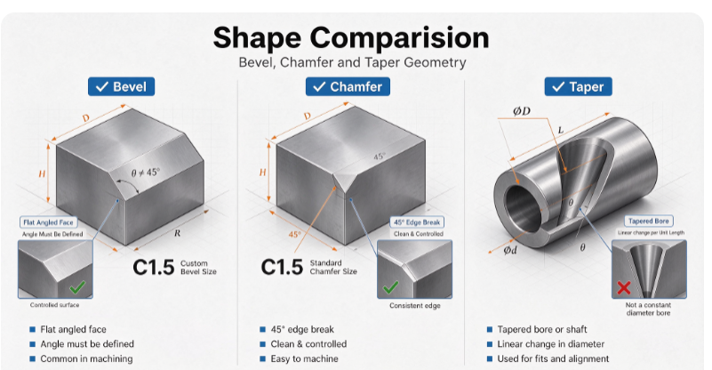
4. Bevel vs Chamfer: What Is the Difference?
Bevel and chamfer are two terms frequently used to describe angled surfaces. The confusion exists partly because general CAD terminology and manufacturing terminology do not always use them consistently. Some CAD tools use chamfer and bevel loosely; the exact behaviour depends on the software version and help documentation.
In general CAD and mechanical machining contexts, a bevel and a chamfer can describe essentially the same flat angled edge. Specialized manufacturing applications may distinguish between them, especially in welding, where the edge preparation is described using terms such as bevel face, bevel angle, root face, and groove geometry.
The practical lesson is simple: do not rely on the feature name alone. Define the actual geometry and dimensions on the engineering drawing.
| Comparison | Bevel | Chamfer |
|---|---|---|
| Geometry | Angled surface | Flat, angled edge transition |
| Typical application | Welding and edge preparation | Deburring and assembly |
| Typical scale | Can extend across a substantial edge or material thickness | Often a localized edge feature |
| Main dimensions | Angle and preparation depth | Distance and angle |
| CNC machining | May require angled setup or specialized tooling | Often produced with chamfer cutters |
| Welding | Commonly specified | May be distinguished from bevel in joint terminology |
| CAD terminology | Sometimes synonymous with chamfer | Often a specific edge feature |
5. Bevel vs Taper: What Is the Difference?
Bevel vs taper is another common source of confusion because both features involve angled surfaces. The key difference is the length and purpose of the geometric transition.
A bevel creates an angled edge or surface, generally by cutting away material at an edge. A taper produces a gradual dimensional change along a functional length.
| Feature | Bevel | Taper |
|---|---|---|
| Geometry | Angled edge or face | Gradually changing cross-section |
| Typical location | Edge or end preparation | Along a component’s length |
| Main purpose | Edge preparation, joining, or design | Fitting, alignment, and functional transition |
| Dimensions | Angle and depth | Taper ratio, end dimensions, length, or angle |
| Typical applications | Plates, panels, welded joints | Shafts, pins, bores, toolholders |
| CNC process | Milling, angled cutting, grinding, or fabrication | CNC turning, milling, grinding, or forming |
Practical Example: Bevel vs Taper on a Steel Shaft
Imagine a cylindrical steel shaft with a diameter of 20 mm. At the end of the shaft, you add a 1 × 45° chamfer. This creates a short angled surface that removes the sharp edge.
Now consider a shaft that gradually changes from 20 mm to 16 mm in diameter over a length of 100 mm. This is a taper.
Although both features contain angled surfaces, their geometry and functional purpose are completely different. A chamfer prepares the shaft end, whereas the taper defines a substantial portion of the shaft’s working geometry.
Expert insight: A chamfer on a cylindrical shaft can mathematically create a short conical surface. That does not automatically make it a functional taper. The intended length, geometry, fit, and drawing requirements determine how the feature should be treated.
6. Difference Between Taper and Chamfer in CNC Machining
Understanding this difference is particularly important for CNC manufacturers because both features can require different machining strategies and inspection methods.
Machining a Chamfer
A chamfer is usually a relatively localized feature. Common machining methods include using a 45-degree chamfer milling cutter, using a countersinking tool, programming an angled toolpath, and performing a secondary edge-finishing operation. For a straightforward external chamfer, the machining process is generally simple. However, chamfers around complex edges or inaccessible features may require additional tool orientations or setups.
Machining a Taper
A taper requires maintaining a specified dimensional relationship over a longer distance. For cylindrical components, CNC turning is a common process: the tool follows a programmed path that gradually changes the diameter along the component’s axis. Other manufacturing options include CNC milling, precision grinding, specialized taper grinding, and forming processes, depending on material and geometry. For high-precision taper components, controlling the angular relationship and dimensional profile is essential.
How Does Taper Affect Inspection?
A chamfer can often be inspected by measuring its edge distance and angle. A functional taper may require more comprehensive measurements: large-end diameter, small-end diameter, taper length, taper angle or ratio, roundness and straightness where required, surface finish, and contact pattern for mating tapered components where applicable.
A part may have the correct diameter at both ends but still fail its taper requirement because the profile between those points is incorrect. This is why taper inspection should not rely exclusively on measuring two endpoint diameters.
7. Bevel vs Chamfer vs Miter: What Is the Difference?
The term miter introduces another source of confusion. Unlike a chamfer or bevel, which typically describes the resulting edge geometry, a miter commonly describes an angled cut or joint used to connect two components. A typical example is two pieces of material cut at 45 degrees and joined to create a 90-degree corner.
Miter joints are widely used in woodworking, architectural frames, metal fabrication, and certain enclosure designs.
What Is a Miter Cut?
A miter cut is an angled cut made so that two components can meet at a specified angle. For example, when constructing a rectangular frame, two adjacent members may be cut at 45 degrees so that they form a 90-degree corner. A miter joint is the resulting connection.
Miter vs Bevel in Cutting Operations
In common woodworking and miter-saw terminology, the two terms refer to different cutting planes. A miter cut is angled across the horizontal plane or width of the workpiece. A bevel cut is angled through the thickness of the workpiece. A compound cut applies both miter and bevel angles in the same cut.
These definitions are particularly useful when interpreting woodworking equipment and fabrication instructions. In general metal fabrication and mechanical drawings, the drawing and manufacturing context should take priority.
| Feature | Bevel | Chamfer | Miter |
|---|---|---|---|
| Main concept | Angled surface | Angled edge treatment | Angled cut or joint |
| Typical purpose | Edge preparation or joining | Edge finishing or assembly | Connecting components at an angle |
| Geometry | Sloping face | Flat, angled edge | Angled end or mating cut |
| Common application | Welded metal plates | CNC machined parts | Frames and enclosures |
| CNC relevance | Angled face machining | Edge machining | Angled part cutting and joining |
When should you use a miter instead of a chamfer? Choose a miter when the design requires two components to meet at a particular angle. Choose a chamfer when the purpose is to remove a sharp edge or create a localized angled transition. These features are not interchangeable simply because both may contain an angled surface.
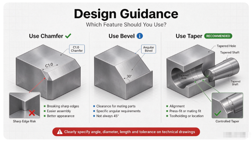
8. Chamfer vs Fillet vs Bevel vs Taper: Complete Comparison
Fillet, chamfer, bevel, and taper are among the most common geometric features encountered in mechanical part design. Each has a different geometric definition and manufacturing purpose. Miter is included because it is commonly grouped with bevel in fabrication terminology, but it is a cut/joint concept rather than a surface feature.
| Feature | Geometry | Main dimension | Typical application |
|---|---|---|---|
| Fillet | Curved transition | Radius (R) | Internal corners and smooth transitions |
| Chamfer | Flat angled transition | Distance and angle | Edge finishing and assembly |
| Bevel | Angled face or edge | Angle and depth | Edge preparation and welding |
| Taper | Gradual size change | Taper ratio and length | Shaft and bore fitting |
| Miter | Angled cut or joint | Cutting angle | Joining components |
Which Feature Is Better for Mechanical Strength?
There is no universal answer because the features perform different functions. However, their geometry influences how mechanical loads are transferred.
- Fillets. Properly designed fillets can reduce localized stress concentrations caused by abrupt geometric transitions. They are particularly useful in structural brackets, load-bearing parts, and components exposed to cyclic loading.
- Chamfers. Chamfers can remove sharp edges, provide clearance, and support assembly. They should not automatically be regarded as structural substitutes for fillets.
- Bevels. A bevel may improve the accessibility and geometry of a welded joint. Its contribution to joint performance depends on the complete welding design and procedure.
- Tapers. Tapers can improve locating, centering, and mechanical engagement in mating components. Their functional performance depends on the taper angle, dimensional accuracy, contact area, and fit.
For critical components, evaluate the geometry using appropriate calculations, material properties, tolerance analysis, and FEA where needed.
9. How to Specify These Features on CNC Engineering Drawings
Correct terminology is important, but clear dimensions are even more important. A CNC manufacturer should not have to guess what a designer intended.
Fillet Specification
A typical fillet callout uses a radius, for example R2.0, indicating a nominal radius of 2.0 mm. For complex or variable-radius transitions, provide additional dimensions or clearly defined CAD geometry.
Chamfer Specification
Common examples include 1 × 45°, 2 × 45°, and 1 × 30°. Specify the dimensioning convention and tolerance when the feature affects assembly or function.
Bevel Specification
For a general machined bevel, provide the bevel angle, bevel depth or dimensions, position, and relevant tolerance. For welding, provide the required groove geometry and applicable welding symbols and specifications.
Taper Specification
A taper should generally include enough information to define its dimensional profile: large-end diameter, small-end diameter, taper length, taper ratio or angle, datum references, dimensional and geometric tolerances, and surface finish where functionally important. For a precision tapered connection, additional requirements may be needed to control contact and mating performance.
Miter Specification
A miter cut or joint should clearly identify the required angle, reference surface or datum, cut direction, component dimensions, fit-up requirements, and relevant tolerances. For assemblies, showing the assembled joint alongside individual part drawings can prevent interpretation errors.
Expert insight: A 3D CAD model communicates shape, but it does not automatically communicate every functional requirement. Use engineering drawings to define critical dimensions, tolerances, surface finish, and inspection requirements.
10. How to Choose the Right Feature: A Practical Design Framework
When preparing a component for CNC machining or fabrication, follow this short decision process. Each step refers back to the detailed sections above.
- Identify the functional purpose. Remove a sharp edge, improve alignment, create a welded joint, change the diameter along a shaft, reduce stress concentration, or connect two parts at an angle?
- Match the function to the feature. Smooth transition → fillet. Localized angled edge → chamfer. Angled preparation or face → bevel. Gradual dimensional change → taper. Angled joint → miter. Confirm with Sections 1–8.
- Consider the manufacturing process. Evaluate CNC milling, CNC turning, 5-axis CNC machining where applicable, precision grinding, drilling and countersinking, laser or saw cutting, and welding preparation processes.
- Check dimensional and functional requirements. Component fit, positioning accuracy, assembly clearance, contact surfaces, structural performance, weld quality, and surface finish.
- Review manufacturing cost and confirm the drawing. Avoid unnecessarily complicated geometry; confirm that the CAD model, 2D drawing, and functional requirements are consistent. When uncertain, consult your CNC manufacturing supplier before releasing the design for production.
11. Common Design and Manufacturing Mistakes
Even relatively small geometric mistakes can result in unnecessary manufacturing costs or component failures. The five problems below summarize the cautions detailed earlier in the article.
- Using a chamfer where a functional taper is required. A short chamfer cannot replace a long precision taper. The two features have different dimensional and functional requirements.
- Treating bevel and chamfer as universally different. CAD software and general machining terminology may use the terms interchangeably. Specify actual geometry rather than relying on terminology alone.
- Confusing a miter cut with an edge chamfer. A miter is intended to create an angled cut or joint, not simply remove a sharp edge.
- Ignoring taper angle tolerances. A tapered component can have correct endpoint diameters but still have an incorrect angular profile. Specify the taper and inspection requirements clearly.
- Adding unnecessary edge treatments. Every additional feature can introduce machining, inspection, and finishing requirements. Edge geometry should provide a genuine functional, safety, or design benefit.
Frequently Asked Questions
1. What is the main difference between a bevel and a chamfer?
A bevel describes an angled edge or surface, while a chamfer is generally a more specifically defined angled edge treatment. In many CAD and CNC machining applications, the terms overlap and may be used interchangeably. In welding, their meanings can become more specialized — follow the applicable drawing conventions and welding standards.
2. What is the difference between a taper and a chamfer?
A chamfer removes material from a localized edge to create an angled surface. A taper gradually changes the width, thickness, or diameter of a component over a specified length. A chamfer is commonly used for edge finishing and assembly, while a taper is often a functional feature for fitting and alignment.
3. What is the difference between bevel, chamfer, and miter?
A bevel is an angled surface, a chamfer is a localized angled edge treatment, and a miter is an angled cut or joint used to connect components. Although their geometry may look similar in some applications, their intended manufacturing functions are different.
4. Is a tapered edge the same as a beveled edge?
Not necessarily. A beveled edge is generally a localized angled surface, whereas a tapered feature changes dimension gradually over a specified length. A component can have both features, such as a tapered shaft with a small chamfer at its end.
Conclusion: Geometry Matters More Than Terminology
Bevel, chamfer, taper, miter, and fillet may all involve changes in component geometry, but they serve different engineering and manufacturing purposes.
The essential differences are:
- Fillet: a curved transition defined by a radius.
- Chamfer: a localized flat, angled edge treatment.
- Bevel: an angled surface or edge, commonly associated with fabrication and welding.
- Taper: a gradual change in component dimensions along a length.
- Miter: an angled cut or joint used to connect components.
Choosing the correct feature is not just a matter of visual preference. It affects CNC tool accessibility, machining operations, dimensional accuracy, assembly performance, and total production cost.
For engineers and product developers, the best approach is to define each feature according to its functional purpose and confirm that the geometry is compatible with the intended manufacturing process.