CNC Turning-Milling Composite Center
The CNC turning-milling composite center is a type of machine tool developed based on the turning CNC machine, with additional boring and milling capabilities. It features a turning bed, a turning spindle, and an auxiliary spindle for milling and boring operations. The machine primarily focuses on turning, with milling and boring as supplementary functions, hence the name turning-milling composite center.
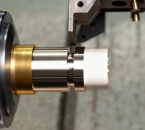
As shown in Figure 1, small and medium-sized turning-milling composite centers have a structure similar to that of a horizontal CNC lathe, with a slanted bed and a turning spindle at the bottom. The turning spindle also includes Cs-axis control and is equipped with accessories such as a tailstock and centers for turning. The upper part of the machine consists of an auxiliary spindle and an automatic tool changer, which adopts the structure of a milling and boring machine, The turning and milling tools use a unified toolholder, and the tools are exchanged by a robotic arm.

The main difference between the turning-milling composite center and the turning center lies in the auxiliary spindle and the automatic tool changer. The turning center, similar to a fully functional CNC lathe, uses a turret toolholder, and tool changes are achieved through turret indexing. The power tools and transmission systems are housed inside the turret. This structure allows for simple tool exchanges with high-speed changes and good tool rigidity. However, for milling and boring operations, the machine has limitations such as a small Y-axis travel, weak milling capability, and a complex auxiliary spindle drive system with a long transmission chain, low spindle speed, and poor rigidity. Therefore, its milling and boring capabilities are relatively weak.
The auxiliary spindle of the turning-milling composite center typically uses a direct motor connection or electric spindle drive, providing a simple, rigid structure with high speeds of up to tens of thousands of RPM. It can also accommodate standard milling and boring tools, greatly improving the machine's milling and boring capabilities.
The auxiliary spindle of the turning-milling composite center can swing through a wide range of about 225° (B-axis), allowing for tool orientation adjustments for both turning and inclined surface milling and boring operations. For example, when the machine is used for internal or external cylindrical or end-face turning, the turning tool is locked into position, and the B-axis is set to 0° or 90° for positioning and clamping. The workpiece rotates with the main spindle, while the X and Z axes control the motion for turning. When the machine is used for side or end-face boring and milling of a rotating body, the turning spindle switches to C-axis control, becoming a CNC rotary axis. At this point, the auxiliary spindle performs boring, milling, and drilling operations on the workpiece mounted on the turning spindle. With five coordinate axes (X, Y, Z, B, and C), the machine is capable of 5-axis machining.
This turning-milling composite center effectively solves the problem of milling limitations in turning centers and enables 5-axis machining. However, its automatic tool changer structure is relatively complex, and the slanted bed design imposes certain limitations on the Y-axis travel. To address these issues, larger turning-milling composite centers sometimes use a column-moving structure similar to a vertical 5-axis machining center, with an A-axis rotary table and a spindle box swing. In this case, the A-axis uses a turning spindle structure, complete with a tailstock and centers, allowing the turning-milling composite machine to fully integrate the turning capabilities of a CNC lathe and the boring-milling capabilities of a milling machine.