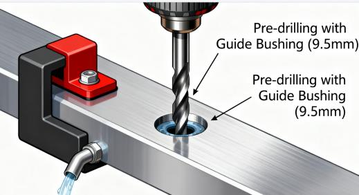
In the realm of industrial manufacturing, threads serve as fundamental components for connection, fixation, and sealing applications. The precision of thread machining directly determines equipment stability, safety, and service life. Among various thread standards, the 3/8-16 UNC thread has emerged as a global benchmark across mechanical manufacturing, automotive, aerospace, and medical device industries due to its optimal balance of strength adaptability, universal compatibility, and mature supply chain infrastructure.
From small equipment bracket fastening to critical engine cover sealing applications, the 3/8-16 UNC thread demonstrates remarkable versatility. However, machining this thread involves far more complexity than simply selecting a tap and drilling a hole. Incorrect drill sizing can lead to stripped threads or tap breakage, while neglecting material properties may cause rapid tool wear in stainless steel or cracking in plastic components due to excessive engagement.
This comprehensive guide systematically deconstructs the machining logic behind 3/8-16 UNC threads across seven critical dimensions: fundamental understanding, dimensional calculations, material compatibility, tool selection, process implementation, quality inspection, and maintenance protocols. Beyond standard applications, we explore specialized solutions for challenging materials, deep-hole machining, and helical coil inserts, empowering engineers, machinists, and procurement teams with systematic machining knowledge.
Section 1: Fundamental Understanding of 3/8-16 UNC Threads: Parameter Definitions and Industrial Significance
1.1 Core Parameter Analysis of 3/8-16 UNC Threads
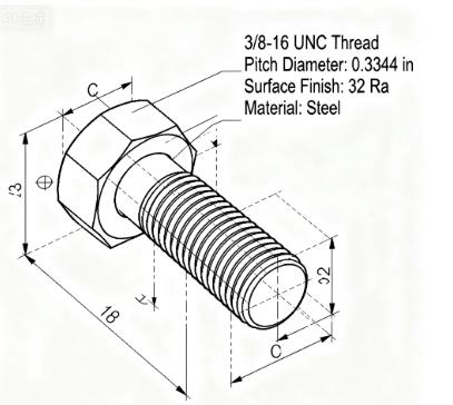
Major Diameter: 3/8 inch (approximately 9.525 mm), representing the outermost diameter of the thread crest, serving as the nominal diameter and matching benchmark for fasteners.
Threads Per Inch (TPI): 16 threads per inch, corresponding to a pitch of 1/16 inch (approximately 1.5875 mm). Coarse threads (UNC) feature fewer TPI and wider thread profiles, offering superior resistance to stripping—particularly beneficial in soft materials like aluminum and brass where vibration or loading might cause thread deformation.
Thread Form: Utilizes a symmetrical 60-degree thread angle, with thread height representing half the difference between major and minor diameters. The standard 3/8-16 UNC thread features a minor diameter of approximately 0.3125 inches (5/16 inches), forming the basis for standard drill size selection.
Fit Class: Commonly employs 2B (internal threads) and 2A (external threads) classifications, representing medium fit accuracy that balances assembly convenience with sealing performance. High-precision applications (aerospace) may require 3B/3A classifications with stricter tolerance requirements for pitch diameter and thread angle.
1.2 The Industrial Dominance of 3/8-16 UNC Threads
The widespread adoption of 3/8-16 UNC threads across multiple industries stems from its optimal equilibrium between strength, machining difficulty, and cost-effectiveness:
Strength Adaptability: The coarse thread profile provides substantial load-bearing area, with the 3/8-inch diameter capable of withstanding 500-800 MPa tensile strength (material-dependent), satisfying both light equipment fastening requirements and medium structural component loading (industrial motor brackets).
Machining Compatibility: The combination of pitch and diameter in 3/8-16 threads minimizes issues like tap breakage and thread distortion across CNC turning, milling, and manual tapping operations, with moderate equipment precision requirements enabling stable machining even in small-to-medium workshops.
Supply Chain Maturity: Corresponding taps, drills, and fasteners (bolts, nuts) are mass-produced commodities with low procurement costs and short lead times, eliminating the need for specialized tooling and reducing manufacturing barriers.
Section 2: Core Calculations for 3/8-16 Tap Drill Sizes: From Theory to Practice
Pre-drill hole sizing represents the critical first step in 3/8-16 thread machining—oversized holes result in insufficient thread engagement and stripping, while undersized holes increase cutting loads and tap breakage risk. Correct sizing derives from engineering calculations based on thread engagement percentages rather than empirical estimates.
2.1 Drill Size Calculation Principles: Thread Engagement as the Primary Objective
Thread engagement percentage defines the actual contact area between internal (hole) and external (bolt) threads relative to the theoretical total contact area, serving as the crucial determinant of thread strength. Industry consensus identifies 60%-75% as the optimal engagement range:
Below 60%: Insufficient contact area increases risk of bolt loosening or pull-out, particularly in vibrational environments (automotive chassis).
Above 75%: Excessive cutting volume dramatically increases tap torque, accelerating wear or breakage while reducing machining efficiency.
Based on these principles, Unified Thread (UNC/UNF) drill size calculations follow the standardized formula:
Pre-drill Size = Major Diameter - (1 ÷ Threads Per Inch)
2.2 Standard Size Calculation and Verification for 3/8-16 UNC
Applying 3/8-16 parameters to the formula:
Major Diameter = 3/8 inch = 0.375 inch
1 ÷ TPI = 1 ÷ 16 = 0.0625 inch
Pre-drill Size = 0.375 - 0.0625 = 0.3125 inch = 5/16 inch
This dimension corresponds to Letter F drill bit in imperial sizing systems (where letter-designated drills feature specific diameters, with F drill precisely measuring 0.3125 inches), serving as the primary choice for general 3/8-16 thread applications. Across low-carbon steel, aluminum, or brass materials, the 5/16-inch drill achieves approximately 70% engagement, balancing strength with machinability.
2.3 Size Adjustments for Varying Engagement Requirements
Practical machining requires drill size adjustments based on material hardness and strength requirements, with controlled deviations from standard values:
| Engagement Requirement | Application Scenario | Drill Size (inches) | Decimal Equivalent | Material Examples |
|---|---|---|---|---|
| 60%-65% | Hard materials, deep-hole tapping | 21/64 | 0.3281 | Stainless Steel 304, Titanium TC4 |
| 70%-75% | General applications, medium-hard materials | 5/16 (F Drill) | 0.3125 | Low-Carbon Steel Q235, Aluminum 6061 |
| 80%-85% | Soft materials, high-strength requirements | 19/64 | 0.2969 | Brass H62, ABS Plastic, Polypropylene |
Critical Note: Adjustment ranges should not exceed ±0.0156 inches (approximately 0.4 mm), as larger deviations may cause thread parameters to exceed 2B/3B tolerance specifications. For example, using 17/64-inch (0.2656 inch) drills for plastic components may increase engagement but risks tap breakage due to material compression.
Section 3: Material Property Impacts on 3/8-16 Tap and Drill Selection
Material characteristics—hardness, plasticity, thermal conductivity—directly determine optimal combinations of drill sizes, tap types, and cutting parameters. Identical 3/8-16 thread specifications require completely different machining approaches for stainless steel versus plastic materials, with material property neglect being a primary cause of machining failures.
3.1 Soft Materials (Hardness ≤150 HB): Chip Control and Engagement Management
Soft materials like Aluminum 6061, Brass H62, ABS plastic, and polypropylene present machining challenges related to chip adhesion and material deformation, requiring "smaller drills + anti-adhesion taps" solutions:
Drill Size Selection: Prefer 19/64-inch (0.2969 inch) drills achieving approximately 80% engagement—soft materials experience thread deformation under pressure, with higher engagement percentages improving strip resistance. For crack-prone plastics (PVC), standard 5/16-inch drills reduce radial pressure during tapping.
Tap Types: Recommended spiral point taps or roll form taps:
- Spiral Point Taps: Feature forward-facing chip ejection channels (ideal for through-holes), preventing chip accumulation in thread forms.
- Roll Form Taps: Utilize chipless thread forming through material plastic deformation, suitable for ductile aluminum and copper with superior surface finish (Ra≤0.8μm) and no chip evacuation concerns (blind holes).
Cutting Parameters: 800-1500 RPM spindle speeds, feed rates = RPM × pitch (e.g., 1000 RPM × 0.0625 inch/rev = 62.5 inches/minute); light mineral oils or synthetic cutting fluids preferred over high-viscosity oils (chip adhesion risk).
3.2 Medium-Hard Materials (150-300 HB): Balancing Cutting Forces and Tool Life
Medium-hard materials including low-carbon steel Q235, annealed stainless steel 304, and cast iron HT200 present moderate cutting resistance with built-up edge formation tendencies, requiring "standard drills + coated taps" for efficiency-longevity balance:
Drill Size Selection: 5/16-inch (F drill) represents the optimal solution, with 70% engagement ensuring strength without excessive tap loading. For stainless steel 304 (poor thermal conductivity, high cutting temperatures), consider 21/64-inch drills to reduce cutting volume and tap temperatures.
Tap Types: Prioritize TiN-coated spiral flute taps:
- Spiral Flute Taps: Upward-angled flutes evacuate chips from blind hole bottoms, preventing tap breakage from chip compression.
- TiN Coating: HV2000 hardness provides exceptional wear resistance, reducing friction with stainless steel and extending tool life 2-3× compared to standard HSS tools.
Cutting Parameters: 500-800 RPM (lower range for stainless, upper for mild steel), synchronized feed rates; soluble oil cutting fluids (5%-10% dilution) provide both cooling (heat dissipation) and lubrication (built-up edge prevention).
3.3 Hard Materials (≥300 HB): Load Reduction and Thermal Management
Hard materials like solution-treated stainless steel 316, titanium TC4, and tool steel Cr12 present challenges of high hardness, elevated cutting temperatures, and rapid tap dulling, requiring "larger drills + carbide taps" for load reduction:
Drill Size Selection: Mandatory use of 21/64-inch (0.3281 inch) drills maintaining 60%-65% engagement—hard materials generate 3-5× higher cutting forces than soft materials, with excessive engagement accelerating tap crest wear and pitch diameter deviation.
Tap Types: Cobalt high-speed steel (HSS-E) or tungsten carbide (WC-Co) taps:
- HSS-E Taps: 5%-8% cobalt content provides high hot hardness (HRC60 at 600°C), suitable for batch stainless steel 316 machining.
- Carbide Taps: HRC70+ hardness offers exceptional wear resistance but requires rigid tapping (precise spindle-feed synchronization) to prevent brittle fracture from vibration.
Cutting Parameters: 300-500 RPM (≤300 RPM for titanium), 10%-15% reduced feed rates (e.g., 300 RPM × 0.0625 inch/rev = 18.75 inches/minute); extreme-pressure neat oils (sulfur/phosphorus additives) form lubricating films under high temperatures, reducing tap wear.
3.4 Composite Materials (CFRP, GFRP): Delamination Prevention and Precision Maintenance
Carbon fiber-reinforced plastic (CFRP) and glass fiber-reinforced plastic (GFRP) composites present machining challenges of fiber breakage and matrix delamination, requiring "specialized tools + low speeds":
Drill Size Selection: Approximately standard 5/16-inch, recommended 0.310-inch (custom drills)—composite anisotropy causes fiber pull-out during threading, with oversized drills exacerbating delamination and undersized drills compressing fibers.
Tap Types: Diamond-coated or tungsten carbide taps with honed cutting edges (avoiding sharp edges that sever fibers); manual or low-speed CNC tapping preferred to minimize vibration-induced fiber damage.
Process Details: Implement 45° chamfers (0.5mm depth) before tapping to prevent edge delamination; alcohol-based lubricants (non-corrosive, resin-compatible) recommended over oil-based fluids (matrix penetration risk).
Section 4: Specialized Machining Solutions for 3/8-16 Helical Coil Thread Inserts
When machining 3/8-16 threads in soft materials (aluminum, plastic) or thin-walled components, thread forms may damage under repeated disassembly or high loading—installing helical coil inserts (threaded inserts) enhances connection reliability through high-strength embedded threads. This process differs fundamentally from direct tapping, focusing on compatibility with insert external thread dimensions.
4.1 Helical Coil Operating Principles and Types
Helical coils constitute spring-like thread sleeves manufactured from stainless steel or copper alloys, installed to provide "external threads" engaging component holes and "internal threads" mating with bolts—effectively embedding high-strength thread forms in soft materials. Common variants include:
Free-Running Coils: Internal threads lack locking features, suitable for static load applications (equipment enclosure fastening).
Self-Locking Coils: Internal threads incorporate 1-2 deformed threads creating interference fits with bolts, providing vibration resistance (automotive engine accessories).
4.2 Processing Steps and Dimensional Requirements for 3/8-16 Helical Coils
Helical coil installation follows four critical steps—drilling, tapping, installation, and tang breakoff—each requiring precise dimensional control:
Pre-Drilling: Critical dimension involves hole size compatibility with insert external threads. Standard 3/8-16 helical coils feature external thread specifications of "3/8-16 STI" (Screw Thread Insert), requiring 25/64-inch (0.3906 inch) pre-drill sizes—0.0781 inches larger than direct tapping's 5/16-inch dimension, providing clearance for insert external threads to prevent wall cracking during installation.
Note: Insert brands may feature slight dimensional variations—always consult manufacturer drilling specifications (e.g., specific 3/8-16 self-locking inserts may require 0.391 inch ±0.002 inch holes).
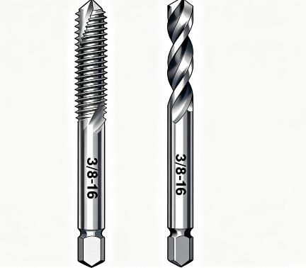
Tapping: Mandatory use of STI-specific taps featuring different thread forms than standard 3/8-16 taps—STI taps exhibit greater thread height with tighter pitch tolerances, ensuring complete insert external thread engagement with hole walls. Tap depth should exceed insert length by 1-2 pitches (e.g., 0.5-inch insert requires 0.5 + 0.0625×2 = 0.625 inch depth), preventing incomplete insert seating.
Insert Installation: Utilize dedicated installation tools (guide mandrels and sleeves) to thread inserts into prepared holes until installation tangs flush with component surfaces; maintain 20-30 N·m installation torque (upper range stainless inserts, lower copper inserts)—excessive torque causes distortion, insufficient torque risks loosening.
Tang Breakoff: Free-running inserts require tang removal using breakoff tools (pre-weakened fracture points); self-locking variants typically lack tangs, ready for immediate use.
4.3 Common Helical Coil Machining Errors and Prevention
Error 1: Using standard 3/8-16 taps for STI holes.
Consequence: Insert external threads fail to engage properly, causing loosening or complete pull-out.
Error 2: Selecting drill sizes based on standard tapping (5/16 inch).
Consequence: Inserts cannot thread into holes, with forced installation cracking hole walls and scrapping components.
Error 3: Neglecting tang breakoff after installation.
Consequence: Tangs interfere with bolt installation, preventing proper seating and compromising connection strength.
Section 5: High-Precision 3/8-16 Thread Machining in CNC Environments
CNC machining represents the primary method for 3/8-16 thread batch production, offering superior precision and consistency through optimized parameters, fixture design, and error compensation—particularly critical for high-precision applications (aerospace components with ≤0.02 mm thread position tolerances).
5.1 Parameter Optimization: Speed, Feed, and Depth Synchronization
CNC tapping parameters require adjustment based on material, tap type, and hole configuration (through/blind), with core emphasis on maintaining perfect spindle-feed synchronization (rigid tapping) to prevent pitch errors:
| Material Type | Tap Type | RPM | Feed Rate (ipm) | Tap Depth (inches) | Hole Type |
|---|---|---|---|---|---|
| Aluminum 6061 | Form Tap | 1200 | 75 (1200×0.0625) | Thread length + 0.125 | Blind |
| Mild Steel Q235 | TiN Plug Tap | 800 | 50 (800×0.0625) | Thread length + 0.0625 | Through |
| Stainless 304 | HSS-E Spiral | 500 | 31.25 (500×0.0625) | Thread length + 0.125 | Blind |
| Titanium TC4 | Carbide Tap | 300 | 18.75 (300×0.0625) | Thread length + 0.1875 | Blind |
Depth Control Techniques: Blind holes require chip clearance space—depth = effective thread length + 1.5×pitch (e.g., 0.5 inch length → 0.5 + 1.5×0.0625 = 0.59375 inches); through holes should extend 0.5×pitch beyond part backsides ensuring complete thread formation.
5.2 Tapping Method Selection: Rigid vs. Flexible Tapping
CNC tapping employs two primary methodologies selected according to machine precision and hole depth requirements:
Rigid Tapping: CNC system synchronizes spindle rotation with axis movement in real-time (angular position precisely matching linear travel), eliminating need for floating holders and providing superior accuracy (pitch error ≤0.001 inch), ideal for high-precision components (medical devices) and shallow holes (depth ≤2×diameter).
Requirements: Machine must support rigid tapping functionality with rigid tool holders (ER collets) preventing holder movement causing synchronization errors.
Flexible Tapping: Floating holders compensate for minor spindle-feed mismatches, suitable for deep holes (depth >3×diameter) and less rigid machines (older mills).
Note: Float should not exceed 0.1 mm to prevent pitch diameter deviations; flexible tapping accuracy falls short of rigid methods, unsuitable for 3B class threads.
5.3 Fixturing and Positioning Accuracy Control
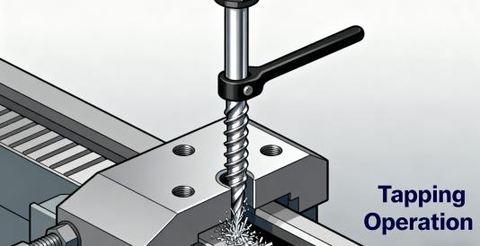
Thread position and perpendicularity represent critical CNC machining metrics (e.g., automotive transmission cover threads requiring ≤0.01 mm perpendicularity), achieved through fixture optimization:
Location Datum: Prioritize component design datums (planes, holes) as reference surfaces preventing errors from datum misalignment—e.g., bracket 3/8-16 threads should reference mounting surfaces with ≤0.005 mm flatness.
Clamping Methods: Soft materials (aluminum) utilize soft jaws preventing surface damage; hard materials (stainless) employ hydraulic fixtures ensuring uniform clamping force (force = material yield strength × contact area ×1.2), preventing workpiece displacement during machining.
Pre-Drill Accuracy: Pre-drill hole tolerances should maintain ±0.003 inches with perpendicularity ≤0.005 mm—consider drill-reamer sequences improving hole quality before tapping operations.
Section 6: Cutting Fluid Critical Functions and Selection for 3/8-16 Thread Machining
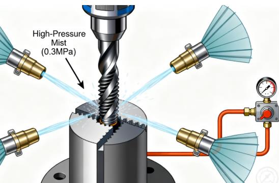
Cutting fluids serve as "invisible tools" in 3/8-16 thread machining—reducing friction, controlling temperatures, improving thread quality, and extending tool life. Particularly with hard materials, omitting cutting fluids may reduce tap life by over 50%.
6.1 Four Core Functions of Cutting Fluids
Lubrication: Forms oil films between taps and workpieces reducing friction coefficients (from 0.3 to below 0.1), decreasing tapping torque and preventing tap crest wear.
Cooling: Dissipates heat from cutting zones (tapping stainless steel may exceed 600°C), preventing tap softening (HSS softening temperature ≈550°C) and workpiece thermal distortion.
Chip Evacuation: Fluid flow removes chips from thread holes preventing chip accumulation between thread forms causing distortion or tap breakage.
Corrosion Prevention: Forms protective films on workpieces and tools preventing post-machining rust (humid environments) and tool corrosion.
6.2 Cutting Fluid Selection Guide for 3/8-16 Threading
Different materials require specific lubrication and cooling characteristics:
| Material Type | Primary Need | Recommended Fluid | Key Specifications | Usage Notes |
|---|---|---|---|---|
| Aluminum/Copper | Anti-adhesion, corrosion prevention | Synthetic fluids (pH8-9) | Chloride ≤50 ppm (aluminum protection) | Maintain concentration (5%-8%), avoid over-dilution |
| Mild Steel | Cooling, rust prevention | Soluble oils (10% dilution) | Rust protection ≥7 days (indoor) | Avoid hard water mixing (scum formation) |
| Stainless Steel | EP lubrication, heat resistance | Neat oils (sulfur/phosphorus) | Flash point ≥180°C (fire safety) | Post-cleaning required (oil film removal) |
| Titanium Alloys | High-temp lubrication, oxidation prevention | EP synthetic fluids | Antioxidants ≥5% | Filtration required (20μm), contamination control |
| Plastics/Composites | Delamination prevention, non-corrosive | Alcohol-based or dry lubricants | Non-resin dissolving | Prohibit oil-based fluids (matrix penetration) |
6.3 Cutting Fluid Application and Maintenance Techniques
Concentration Control: Soluble oils and synthetic fluids require precise dilution—excessive concentration increases viscosity impairing chip evacuation, while insufficient concentration reduces lubrication and corrosion protection. Use refractometers for weekly concentration checks.
Filtration and Cleanliness: Implement magnetic separators (ferrous chips) and paper filters (contaminants) preventing chip accumulation in fluids causing tap wear; monthly sump cleaning removes sediment preventing bacterial growth (humid environments).
Replacement Cycles: Standard fluids require 3-6 month replacement, extreme-pressure fluids (stainless, titanium) 6-12 months; immediately replace fluids showing odor, discoloration, or oil separation signs.
Section 7: 3/8-16 Thread Quality Inspection and Defect Resolution Strategies
Post-machining thread quality requires comprehensive verification preventing defective threads entering assembly processes, with dedicated solutions addressing common issues (stripping, burrs) reducing scrap rates.
7.1 Core Inspection Metrics and Tools
Dimensional Accuracy: Includes pitch diameter, major diameter, and minor diameter compliance with 2B or 3B class tolerances (3/8-16 UNC 2B internal thread pitch diameter tolerance: 0.3340-0.3420 inches).
Inspection Tools: Thread micrometers (pitch diameter, 0.001 inch accuracy), thread plug gages (GO/NO-GO gages—GO must pass, NO-GO must not pass).
Position and Perpendicularity: Position compliance with drawing specifications (±0.02 mm), perpendicularity ≤0.01 mm/10 mm.
Inspection Tools: CMM (batch inspection, 0.0005 inch accuracy), perpendicularity gages (individual part verification, high efficiency).
Surface Quality: Complete thread forms without chipping, burrs, or scratches, surface roughness Ra≤1.6μm (general) or Ra≤0.8μm (high-precision).
Inspection Tools: Surface roughness testers (crest/root measurements), metallurgical microscopes (thread form integrity, micro-defect detection).
Strength Verification: Pull-out testing determines thread resistance—install matching bolts in 3/8-16 threads applying axial tension until failure, recording maximum force (e.g., aluminum 6061 threads should withstand ≥15 kN).
7.2 Common 3/8-16 Thread Defects and Solutions
| Defect Type | Root Causes | Corrective Actions |
|---|---|---|
| Stripped Threads | 1. Oversized drill, <60% engagement; 2. Insufficient material strength | 1. Smaller drill (5/16→19/64); 2. Install helical coils |
| Tap Breakage | 1. Undersized drill, excessive load; 2. Poor chip evacuation | 1. Larger drill (5/16→21/64); 2. Spiral flute taps + high-pressure coolant |
| Thread Burrs | 1. Dull tap, poor edge sharpness; 2. Insufficient coolant | 1. Sharpen or replace tap; 2. Increase coolant pressure (10-15 bar) |
| Pitch Errors | 1. CNC spindle-feed mismatch; 2. Tap pitch deviation | 1. Calibrate rigid tapping parameters; 2. Use ANSI-compliant taps |
| Pitch Diameter Deviation | 1. Tap wear; 2. Excessive tapping torque | 1. Replace tap; 2. Reduce torque (30→25 N·m) |
| Plastic Thread Cracking | 1. Undersized drill, high compressive stress; 2. Excessive speed | 1. Standard 5/16-inch drill; 2. Reduce speed (300-500 RPM) |
7.3 Quality Control Procedures for Batch Production
Ensuring 3/8-16 thread consistency across production batches requires implementing "first-piece - process - last-piece" inspection protocols:
First-Piece Inspection: Machine 1-3 pieces before batch production, complete dimensional, positional, and surface quality verification, confirming parameter validity before full-scale production.
Process Sampling: Inspect 1 piece per 50 units, focusing on pitch diameter and position, immediately stopping for adjustment if deviations occur (tap calibration, parameter optimization).
Last-Piece Inspection: Verify final piece upon batch completion, comparing with first-piece data confirming tool wear within acceptable limits (tap wear ≤0.01 mm).
SPC Statistical Process Control: Utilize SPC software recording thread dimension data per batch, generating control charts (X-R charts) monitoring variation trends, providing early warning of potential issues (gradual deviation indicating impending tap wear).
Section 8: Maintenance and Preservation of 3/8-16 Taps and Drills: Extending Tool Life
Taps and drills represent core consumables in 3/8-16 thread machining, with tool life directly impacting production costs—for example, HSS-E taps costing $8-15 USD can increase lifespan from 500 to 1000 cycles with proper maintenance, significantly reducing per-part costs.
8.1 Tap Maintenance and Preservation Protocols
Post-Use Cleaning: Immediately after tapping, remove chips using compressed air (0.5 MPa pressure), followed by kerosene or diesel cleaning eliminating cutting fluid residues and preventing chip adhesion causing edge corrosion.
Wear Assessment: Evaluate tap condition through "machining feel" and "thread quality":
- Tactile Feedback: Noticeably increased tapping torque (20→30 N·m), irregular rotation indicating wear.
- Quality Indicators: "Tearing" marks on thread surfaces, pitch diameter deviation (NO-GO gage passage).
Tap Reconditioning: Slightly worn taps (wear ≤0.01 mm) can be reconditioned using dedicated tap grinders, addressing cutting edges and flute surfaces, followed by thread form verification (thread gage comparison) ensuring standard compliance.
Storage Methods: Classify taps in anti-corrosion containers preventing impact damage (carbide tap fragility); long-term storage requires rust-preventive oils (industrial vaseline), with quarterly inspection cycles.
8.2 Drill Maintenance and Preservation Protocols
Blunting Indicators: Pre-drilling operations showing "increased diameter deviation" (standard 5/16-inch holes becoming 0.315 inches), "excessive drilling heat" (workpiece surface temperature >100°C), or "powdery chips" (normal chips being spiral-shaped) indicate drill blunting.
Drill Sharpening: Utilize drill grinders reconditioning point angles, chisel edges, and primary relief angles:
- Point Angle: 118° for soft materials, 135° for hard materials ensuring cutting edge sharpness.
- Chisel Edge: Reduce length to 1/3-1/2 original dimensions after grinding, decreasing axial drilling forces.
Corrosion Protection: Dry drills after use preventing rust in humid environments; HSS drills benefit from bluing treatments (oxide film formation) enhancing corrosion resistance; carbide drills require protection from acidic substances (prolonged exposure to diluted cutting fluids).
8.3 Tool Life Management Systems
Establish "tap/drill life ledgers" recording each tool's "usage cycles, machined materials, failure causes," enabling data-driven tool selection optimization:
Example: Data showing "Brand X HSS taps machining stainless 304 fail after 500 cycles" justifies switching to "TiAlN-coated HSS-E taps" extending life to 1000 cycles.
Life Forecasting: When tools reach "80% of rated life," prepare replacement tools preventing production interruptions (e.g., 1000-cycle rated tools replaced at 800 cycles).
Section 9: Industrial Application Case Studies for 3/8-16 Threads
The universal applicability of 3/8-16 UNC threads spans multiple industries, with varying "machining requirements" and "process priorities" across different applications:
9.1 Automotive Industry: Engine Mount Threads (Load-Bearing and Vibration Resistance)
Application Context: Automotive engine mounting threads withstand operational vibrations (200-500 Hz) and weight loads (≈200 kg), demanding high thread strength.
Material: Low-carbon steel Q235 (180 HB), welded to brackets requiring prevention of welding distortion affecting thread accuracy.
Machining Solution:
- Pre-drill: 5/16-inch (F drill) ensuring 70% engagement.
- Tap: TiN-coated plug tap (through-hole), rigid tapping (800 RPM, 50 ipm).
- Cutting Fluid: Soluble oil (10% dilution), balancing cooling and rust prevention.
- Inspection: Focus on perpendicularity (≤0.01 mm) and pull-out strength (≥20 kN), preventing vibration-induced loosening.
9.2 Aerospace: Aluminum Cabin Component Threads (Lightweighting and Fatigue Resistance)
Application Context: Aircraft cabin equipment mounting threads in aluminum 7075-T6 (lightweight, high-strength), requiring helical coil inserts enhancing durability against aluminum thread wear.
Machining Solution:
- Pre-drill: 25/64-inch (STI insert compatibility), drilling followed by reaming (hole tolerance ±0.002 inches).
- Tapping: STI-specific spiral flute taps (upward chip evacuation), flexible tapping (deep holes, 3×diameter depth).
- Insert Installation: Stainless free-running inserts, 25 N·m installation torque, post-tang breakoff insert flush verification (≤0.005 mm).
- Inspection: Fatigue testing (10^6 vibration cycles without loosening), corrosion testing (500-hour salt spray without corrosion).
9.3 Medical Devices: Plastic Housing Threads (Sterility and Burr-Free Requirements)
Application Context: Medical infusion pump housing threads in ABS plastic (non-toxic, machinable), requiring sterility (autoclavable) and burr-free surfaces (operator safety).
Machining Solution:
- Pre-drill: 19/64-inch (increasing engagement to 80%, strip prevention).
- Tap: Form tap (chipless, preventing plastic debris contamination), low-speed tapping (500 RPM, 31.25 ipm).
- Cutting Fluid: Alcohol-based lubricant (volatile, cleaning-free, sterility-compliant).
- Inspection: Surface roughness (Ra≤0.8μm), sterility testing (121°C autoclave without bacterial retention).
Section 10: Frequently Asked Questions (FAQ)
10.1 What considerations are necessary when machining 3/8-16 threads in high-temperature environments (e.g., 200°C)?
Answer: Elevated temperatures soften materials like aluminum or increase hardness in superalloys, requiring adjusted approaches:
- Superalloys (Inconel 718): 21/64-inch drills, carbide taps, EP neat oils, reduced speeds (200 RPM), preventing tap overheating.
- Aluminum Alloys (6061-T6): 5/16-inch drills, form taps, high-temperature synthetic fluids (250°C resistance), immediate post-machining cooling (air) preventing thread distortion.
10.2 How to ensure precision when manually tapping 3/8-16 threads (without CNC equipment)?
Answer: Manual tapping requires "torque control" and "perpendicularity maintenance":
- Pre-drilling: Use drill presses ensuring 5/16-inch holes with perpendicularity ≤0.02 mm (square verification).
- Taps: Hand taps ("taper" then "bottoming" taps—taper for 2/3 depth, bottoming for full depth), uniform force application with tap wrenches preventing misalignment.
- Lubrication: Manual tapping oils (EP additives), periodic reversal (one forward, half reverse) ensuring chip evacuation.
- Inspection: Thread plug gage verification (GO passes, NO-GO fails).
10.3 How to repair 3/8-16 threads with excessive pitch diameter (oversized) after tapping?
Answer: Pitch diameter oversizing typically results from tap wear or excessive torque, with repair strategies depending on deviation magnitude:
- Minor Oversizing (≤0.003 inches): For soft materials (aluminum, copper), re-tap with new taps using reduced torque, utilizing "material compression" reducing pitch diameter.
- Significant Oversizing (>0.003 inches): Install helical coil inserts—enlarge holes to 25/64 inches, tap STI threads, with insert internal threads restoring standard 3/8-16 dimensions.
- Irreparable Cases: Load-bearing or sealing components with oversize threads should be scrapped preventing assembly failures.
10.4 How to extract broken taps from 3/8-16 blind holes?
Answer: Broken tap extraction requires careful execution preventing hole wall damage:
- Protruding Tap Fragments: Use "tap extractors" (reverse-fluted tools) engaging tap flutes for counterclockwise removal; if flutes inaccessible, weld extraction rods to fragments for removal.
- Subsurface Fragments: Employ electrical discharge machining (EDM) disintegrating tap material, followed by hole cleaning and re-tapping with new taps.
- Prevention: Blind holes require chip clearance, spiral flute taps, and avoidance of bottom contact causing fracture.
Conclusion: 3/8-16 Thread Machining—Precision Through Systematic Thinking
3/8-16 UNC thread machining appears deceptively simple yet constitutes a systematic engineering challenge integrating material properties, tool selection, process parameters, and quality control—from standard 5/16-inch drill selection to 21/64-inch adjustments for stainless steel; from rigid tapping precision to cutting fluid lubrication; from thread gage verification to helical coil installation and repair. Each step demands scenario-specific solutions based on practical requirements.
For engineers and machinists, mastering 3/8-16 thread machining logic not only resolves immediate production issues but establishes "universal threading methodology"—enabling high-precision, efficient machining across any thread specification (1/4-20, 5/16-18) through systematic "parameter calculation - material adaptation - process optimization" workflows.
Ultimately, thread precision transcends "dimensional compliance" to "application suitability"—automotive bracket threads require vibration resistance, aerospace components demand fatigue endurance, medical device threads need sterility. Only by integrating "machining precision" with "practical scenarios" can truly reliable products be manufactured.
