How to ensure the accuracy and precision of CNC machining?
To achieve high accuracy (alignment with ideal values) and precision (consistency across multiple iterations) in CNC machining, a deep integration of traditional processes and intelligent technologies is essential. This involves hardware optimization, real-time monitoring, and dynamic compensation to establish a comprehensive quality control system throughout the entire machining process. Below are the detailed implementation strategies:
1. Machine Tool Hardware and Baseline Calibration: The Foundation of Precision
High-Rigidity Machine Selection and Core Component Optimization
The fundamental performance of the machine tool determines the upper limit of precision. Priority should be given to models equipped with precision ball screws (pre-tensioned to eliminate backlash), linear guides (friction coefficient ≤ 0.001), and high-dynamic spindles (radial runout ≤ 0.001 mm). According to GB/T standards, precision-grade (M-grade) machining centers must have a positioning accuracy ≤ 0.012 mm and repeatability ≤ 0.008 mm, while high-precision-grade (G-grade) machines can achieve positioning accuracy within 0.004 mm, making them suitable for micron-level applications such as aerospace. Regular calibration using laser interferometers is necessary to measure axis positioning errors, and built-in error compensation functions should be used to correct pitch errors and backlash, minimizing deviations between commanded and actual positions (improving accuracy).
Thermal and Geometric Error Control
Temperature variations during operation cause thermal deformation. Real-time thermal error compensation systems can dynamically correct this: temperature sensors installed on critical components (e.g., bed, ball screws) combined with AI algorithms predict thermal expansion (e.g., steel expands at 11.5 × 10⁻⁶ mm/m per °C) and automatically adjust machining coordinates. Additionally, a ballbar tester can detect quadrant errors during circular interpolation, and servo parameters can be optimized to reduce contour deviations, ensuring shape accuracy in complex machining paths.

(Image Captions:Thermal and Geometric Error Control)
2. Intelligent Monitoring and Real-Time Compensation: Dynamic Precision Assurance
AI-Driven Machining Process Optimization
AI-enabled CNC systems enable three core functions:
- Adaptive Cutting Parameter Adjustment: Using sensor data (e.g., vibration, spindle current; sampling frequency ≥ 1 kHz), the system identifies material hard spots or tool wear in real time and automatically adjusts feed rates or spindle speeds (e.g., reducing feed by 20% when cutting force spikes occur) to prevent dimensional fluctuations.
- Tool Lifecycle Management: Intelligent monitoring systems (e.g., “Demon Cutter Catcher”) analyze cutting force characteristics to predict remaining tool life, providing a 15-minute advance warning for tool changes to avoid batch defects caused by tool breakage.
- Quality Prediction and Self-Correction: Models trained on historical machining data predict dimensional errors in real time (with ±1 μm precision) and automatically compensate for deviations via tool length adjustments, achieving “first-part correctness.”
Multi-Dimensional Real-Time Error Compensation
A hybrid feedforward + feedback control strategy addresses dynamic errors:
- Feedforward Control: Pre-calculates inertial errors based on the toolpath and pre-adjusts servo motor output.
- Feedback Control: Uses linear encoders (resolution: 0.1 μm) to capture actual positions in real time and corrects feed rates by comparing them to commanded values.
For example, during precision boring, the system can compensate for 0.002 mm deviations caused by workpiece clamping deformation, ensuring bore diameter accuracy.

(Image Captions:Intelligent Monitoring and Real-Time Compensation)
3. Process Design and Fixturing Optimization: Systematic Error Elimination
Rigid Process Planning and Path Optimization
Adhere to the “roughing and finishing separation” principle: roughing uses large depths of cut (ap = 2–5 mm) for rapid material removal, minimizing subsequent deformation; finishing employs low feed rates (f = 0.05–0.1 mm/rev) and high spindle speeds (n = 8,000–15,000 rpm) to achieve surface roughness ≤ Ra 0.8 μm. Toolpaths should avoid frequent direction changes (e.g., using clockwise circular interpolation in milling) to reduce backlash effects on positioning accuracy. CAM software should simulate cutting force distribution to optimize entry points and prevent workpiece chatter.
Modular Fixturing and Datum Consistency
Use modular fixtures (e.g., EROWA/3R; repeatability ≤ 0.001 mm) to ensure consistent datums across batch productions (improving precision). Control clamping force with torque wrenches (e.g., 50–80 N·m for aluminum alloys) to avoid deformation. Machine probes can automatically align workpiece zero points, reducing manual alignment errors from 0.01 mm to within 0.002 mm (improving accuracy). For thin-walled parts, use auxiliary supports or filler materials to minimize deflection errors caused by cutting forces.

(Image Captions:Process Design and Fixturing Optimization)
4. Environmental Control and Periodic Maintenance: Ensuring Long-Term Stability
Thermal and Vibration Isolation
Maintain a workshop environment of 20 ± 2°C and 50 ± 5% humidity to prevent thermal deformation (e.g., a 1°C temperature gradient over a 10 m bed can cause 0.1 mm error). Install air spring vibration isolators under machines to limit external vibration amplitudes to below 0.001 mm, preventing chatter that affects surface finish.
Preventive Maintenance System
Implement a predictive maintenance plan based on vibration spectrum analysis:
- Weekly checks of ball screw lubrication; monthly encoder calibration for servo motors.
- AI analysis of spindle vibration data to early detect bearing wear trends (e.g., scheduling replacement when abnormal 120 Hz vibrations occur).
Use heat-shrink tool holders (clamping repeatability ≤ 0.002 mm) and tool setters to automatically measure and compensate for tool mounting deviations.

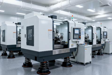
(Image Captions:Environmental control and installation of anti-vibration pads)
5. Closed-Loop Inspection and Continuous Improvement: Iterative Precision Enhancement
Full-Process Quality Inspection
After the first part is machined, use a CMM (accuracy ≤ 0.001 mm) to inspect critical dimensions and generate error reports. During batch production, inspect 3 parts hourly and perform SPC statistical analysis to monitor dimensional dispersion (CPK ≥ 1.33). Incorporate on-machine probing to measure features like holes and steps in real time, automatically compensating for coordinate system deviations (e.g., instant compensation for 0.003 mm X-axis offset).
Data-Driven Process Optimization
Build a machining parameter database recording optimal cutting parameter combinations for different materials (e.g., 7075 aluminum, TC4 titanium). Use big data analytics to identify error patterns (e.g., “dimensions increase by 0.002 mm after 50 parts”), pre-adjust tool life parameters, or modify compensation values, forming a closed-loop “machine-inspect-optimize” iteration.
The Essence of Precision Control Is “System Anti-Interference”
Ensuring accuracy and precision in CNC machining hinges on building an anti-interference system through hardware rigidity, real-time monitoring, and intelligent compensation. Traditional techniques safeguard baseline precision, while AI and IoT technologies overcome dynamic error limitations. In practice, balance cost and performance based on part tolerance requirements (e.g., IT5 demands G-grade machines + AI compensation; IT8 can use M-grade machines) to achieve both “consistency within tolerance” and “alignment with target values.”