CNC Machining Design Guideline – Engineering Standard

| Design Feature | Recommended Value | Acceptable Limit | Engineering Notes |
|---|---|---|---|
| Internal Fillet Radius | R ≥ 1.5 mm | R ≥ 0.8 mm | Standard end mills usable above 1.5 mm |
| Sharp Internal Corners | Not recommended | Functional surfaces only | Requires corner tools or EDM |
| Slot Width | ≥ Tool Diameter | ≥ 0.6 × Tool Diameter | Narrow slots increase tool deflection |
| Deep Pockets / Slots | ≤ 3 × Tool Diameter | ≤ 4 × Tool Diameter | Step machining required beyond 3D |
| Thin Wall (Metal) | ≥ 1.0 mm | ≥ 0.8 mm | Ensures dimensional stability |
| Thin Wall (Plastic) | ≥ 1.8 mm | ≥ 1.5 mm | Prevents thermal deformation |
| Feature | Recommended | Acceptable Limit | Engineering Notes |
|---|---|---|---|
| Hole Diameter | ISO Standard Drills | Non-standard allowed | Non-standard holes require boring |
| Hole Tolerance | H7 | H6 | H6 requires precision boring |
| Blind Thread Depth | ≤ Hole Depth − 1 × D | ≤ Hole Depth − 0.5 × D | Ensures safe tapping |
| Thread Type | M3–M12 | Inch threads supported | Confirmation required |
| Minimum Thread | M2.5 | M2 | Below M2 increases risk |
| Category | Specification | Typical Application | Cost Impact |
|---|---|---|---|
| General Tolerance | ISO 2768-m | Non-critical features | Optimal |
| Precision | ±0.02 mm | Mating surfaces | Medium |
| High Precision | ±0.01 mm | Functional critical surfaces | High |
| Ultra Precision | ≤ ±0.005 mm | Special applications | Engineering review required |
| Surface Roughness | Ra 3.2 ~ Ra 0.4 | Structural to mirror finishes | Depends on requirement |
| Rapid Model Pre-Submission Engineering Checklist | |
|---|---|
| Internal Radius ≥ 1.5 mm | |
| Cavity Depth ≤ 3 × Tool Diameter | |
| Use Standard Hole Diameters | |
| Only Critical Dimensions Have Tolerances | |
| Avoid Thin Wall + Deep Cavity Overlap | |
Engineering Position Statement:
“Designs within the recommended range ensure optimal cost, lead time, and quality. Designs beyond the limit values are subject to engineering review.”
This statement serves to emphasize that Rapid Model does not reject orders outright but maintains control over engineering quality and risk management.
| Surface Roughness Capability | ||
|---|---|---|
| Ra Value | Capability Status | Typical Use |
| Ra 3.2 | Standard | Structural components |
| Ra 1.6 | Stable | Appearance parts |
| Ra 0.8 | Achievable | Mating surfaces |
| Ra 0.4 | Review Required | Mirror-like finishes |
| Cost & Lead Time Optimization | ||
|---|---|---|
| Item | Optimal Design Choice | Engineering Rationale |
| Fixturing | One-side or two-side | Three or more setups increase lead time |
| Feature Layout | Centralized | Reduces re-orientation |
| Part Marking | Laser engraving | CNC engraving for large text only |
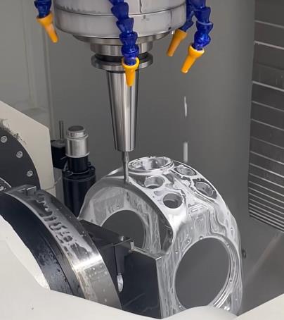
| Freeform Surfaces | Simplified | 5-axis used only when necessary |


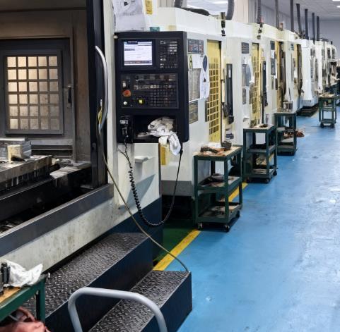
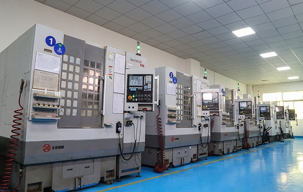
We strictly respect customer privacy; only real events are recorded in case studies without disclosing any customer information.
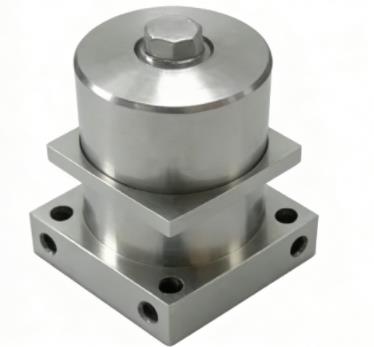
Made from stainless steel and aluminum materials, utilizing precision machining technology with a tolerance of ±0.01. After heat treatment and finishing, the parts are delivered satisfactorily and have received consistent positive feedback.

Delivering prototypes within a short timeframe while meeting extremely strict tolerance requirements and complex geometries, enhancing the overall performance of the drones.
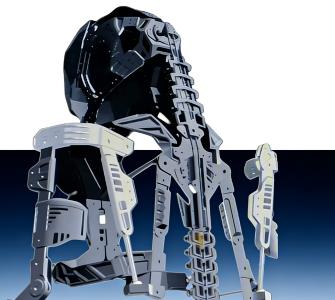
Six high-precision robotic joint connectors manufactured from titanium alloy, processed with 5-axis CNC machining and precise inspection, delivered reliably and highly recognized.
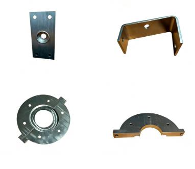
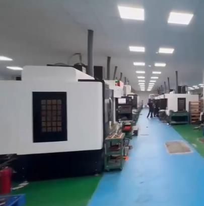
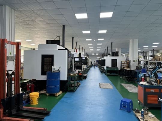
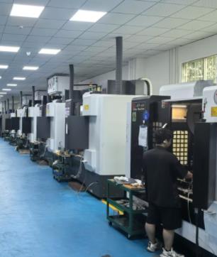
Manufacturing processes include CNC precision machining, 5-axis machining, sheet metal fabrication, and assembly support. Efficient communication greatly shortens delivery lead times
We provide CNC manufacturing services and professional industry solutions for various application sectors.
We provide CNC manufacturing services and professional industry solutions for various application sectors.


