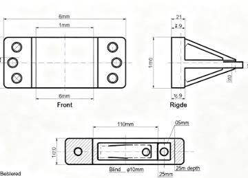
Design for Manufacturing (DFM) represents a paradigm shift in how we approach product development. By embedding manufacturing feasibility logic at the design source, DFM principles enable engineers to significantly reduce design iterations, eliminate production bottlenecks, and achieve substantial time and cost savings throughout the CAD-to-CNC workflow.
What is CAD Design?
CAD (Computer-Aided Design) is the process of using software such as AutoCAD and SolidWorks to create digital drawings and models. It replaces traditional hand-drawing methods, achieving higher precision and efficiency in designing from 2D drawings to 3D models. CAD is widely used in mechanical engineering, architecture, electronics, and other fields.
2D CAD Design
Core Function: Create flat drawings that convey dimensions, tolerances, and annotations.
Common Software: AutoCAD, ZWCAD.
Typical Applications:
- Mechanical part engineering drawings (hole sizes, surface roughness marks)
- Architectural floor plans (room dimensions, doors and windows placement)
- PCB layout design (component placement)
3D CAD Design
Core Function: Build three-dimensional models to visually present spatial structures and support downstream analysis and manufacturing.
Common Software: SolidWorks, UG NX, Creo.
Typical Applications:
- 3D models of mechanical parts (gears, shafts)
- Product appearance design (phone casings, home appliance shells)
- 3D architectural layouts (furniture arrangement and spatial hierarchy)
What is DFM?
DFM (Design for Manufacturability) is a design approach that considers the feasibility, efficiency, and cost of manufacturing during the product design stage. Its goal is to achieve “design for manufacturability and low-cost production.”
Core Objectives of DFM
- Minimize manufacturing complexity: Avoid designs requiring special processes or equipment, enabling parts to be machined with conventional tools.
- Minimize production waste: Reduce material scrap, labor loss, and tooling investment, especially for low-volume production.
- Minimize design iteration: Prevent post-design modifications due to manufacturability issues, shortening the cycle from CAD to CNC production.
Practical Implementation of DFM
- Embedded Design Principles: Apply DFM rules during CAD modeling, e.g., confirm drill size before creating holes.
- Cross-Department Review: After the initial design, involve manufacturing and process engineers to evaluate machinability and cost-effectiveness.
- Simulation Verification: Use software like SolidWorks CAM or UG NX to simulate machining processes, detecting potential tool collisions or overcuts in advance to avoid scrap in actual production.
CAD Design Stage: Preventing Manufacturing "Traps"
The CAD design phase serves as the foundation for cost control, with DFM optimization at this stage potentially eliminating up to 80% of subsequent manufacturing issues. Key considerations include simplifying hard-to-machine features, standardizing dimensions and tolerances, and selecting materials compatible with efficient machining processes.
Design Review Stage: Bridging Information Gaps
The design review phase creates a critical bridge between design intent and manufacturing reality. By involving CNC engineers early and utilizing simulation tools, teams can identify potential issues before they reach the shop floor, preventing costly rework and material waste.
CNC Preparation Stage: Accelerating Production Readiness
DFM principles directly optimize CNC preparation workflows, minimizing equipment setup and waiting times. Strategic decisions regarding machining datums, tool paths, and fixture compatibility can dramatically reduce non-cutting time and enhance overall equipment effectiveness.
CAD to CNC DFM Stage Checklist
| Stage | Check Item | Judgment Standard | Cost Impact |
|---|---|---|---|
| CAD Design | Deep cavity avoidance | Depth ≤ 4× diameter ratio | 40% cost saving vs. EDM |
| Feature accessibility | No internal sharp corners or undercuts | Eliminates special tooling | |
| Radius standardization | All radii ≥ 0.5mm | Reduces tool breakage | |
| Dimension unification | 2-3 standard sizes for holes/slots | 30% setup time reduction | |
| Tolerance optimization | IT9 for non-critical surfaces | 20% machining time saving | |
| Material selection | 6061 aluminum vs. 304 stainless steel | 2× faster machining | |
| Design Review | CNC engineer involvement | Review before final CAD approval | Eliminates $500 custom fixtures |
| Tool path simulation | No collisions or gouging detected | Prevents material scrap | |
| Fixture compatibility | Uses standard vise/clamp systems | No custom fixture costs | |
| Drawing clarity | All dimensions referenced to single datum | 1-2 hours/batch time saving | |
| Surface finish specification | Ra values specified (not "high finish") | Eliminates rework | |
| CNC Preparation | Unified machining datum | Single reference plane/feature | 10-15 min/setup saving |
| Feature grouping | Similar operations clustered together | 25% air-cut reduction | |
| Standard tooling utilization | Design fits existing tooling capacity | 30 min/batch adjustment saving | |
| Tool path optimization | Minimal rapid movements between features | 15% efficiency improvement | |
| Setup simplification | Single setup for multiple operations | Reduces cumulative error |
Conclusion
Implementing DFM principles throughout the CAD-to-CNC workflow represents a strategic approach to manufacturing optimization. The systematic application of these guidelines enables organizations to achieve remarkable efficiency gains—typically reducing setup times by 30%, decreasing machining time by 15-25%, and eliminating costly redesign iterations. The provided checklist serves as a practical tool for design engineers to validate their designs against manufacturing constraints before releasing them to production. By making DFM an integral part of the design culture, companies can significantly enhance their competitive advantage through reduced time-to-market, improved quality, and substantial cost savings across the product lifecycle.


