CNC Machining: Core Technologies, Optimized Parameters & Precision Guide
CNC (Computer Numerical Control) machining is the backbone of modern manufacturing. By converting digital instructions into precise mechanical movements, CNC enables the production of complex parts from metals to composites. From aerospace turbine blades requiring micron-level contour accuracy to smartphone frames demanding mirror-finish surfaces, CNC machining demonstrates unmatched adaptability and precision.
The essence of CNC lies in balancing material properties, machine tool performance, and parameter algorithms. Its precision directly determines product reliability. This guide analyzes the full CNC process, parameter optimization, tooling and fixturing strategies, troubleshooting, and future development trends.

(Image description: CNC machining workflow diagram showing the complete process from CAD design to inspection.)
Full Process: From Digital Model to Physical Part
CNC machining transforms virtual designs into physical parts through three critical stages: digital twin verification, physical machining control, and closed-loop calibration. Modern workflows have evolved from trial-and-error cutting to digital pre-simulation, precise execution, and real-time optimization.
2.1 Digital Twin Verification
Designers build 3D CAD models defining geometry and tolerances. Simulation software such as VERICUT creates digital twins of machines, tools, and workpieces. With collision detection accuracy down to 0.01 mm, this stage prevents costly tool or machine crashes.
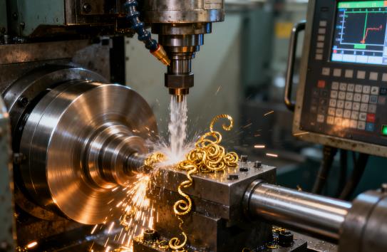
2.2 Dynamic Machining Control
Precision relies on synchronized interaction between machine, fixture, and tool. High-end CNC systems achieve coordinate resolution of 0.1 μm. Fixtures must follow the principle of accurate positioning, reliable clamping, and ease of operation, with positioning element tolerances 1–2 orders higher than part requirements.
2.3 Closed-Loop Calibration
The last defense for quality assurance. The “first-piece triple inspection” combines operator self-check, quality inspector review, and CMM (Coordinate Measuring Machine) verification. CMM accuracy reaches 1 μm, ensuring compliance with dimensional accuracy, geometric tolerances, and surface roughness.

(Image description: A digital twin simulation screenshot containing toolpaths, the machine tool, and the workpiece model.)
Parameter Optimization: Balancing Material, Tool, and Cutting Conditions
Optimizing CNC parameters requires balancing material properties, tool performance, and cutting conditions. A triangle analysis framework ensures high precision and efficiency.
3.1 Aluminum Alloys
High-speed cutting defines aluminum machining. Increasing cutting depth from 0.2 mm to 1 mm raises surface roughness (Ra) from 1.2 μm to 3.5 μm. For finishing, use:
- Cutting depth (ap): 0.1–0.3 mm
- Spindle speed: 10,000–20,000 rpm
- Radial feed (ae) for Ø10 mm end mill: 0.04–0.08 mm
3.2 Titanium Alloys
Titanium alloys behave differently. For TC4:
- Cutting speed (vc): 100–140 m/min
- Feed per tooth (fz): 0.04–0.08 mm/z
- Radial depth (ae): 4.5–5.5 mm
With advanced cooling, cutting zone temperature remains below 300°C, preventing tool adhesion.
Fixtures and Tools: Hardware Foundation for Accuracy
4.1 Fixture Design Principles
Fixtures must integrate positioning, clamping, and guiding. Tolerances of fixture elements should be 1/3–1/5 of part tolerance. Hydraulic systems provide clamping force 1.5–2× cutting force, avoiding deformation.
4.2 Tool Selection and Management
- HSS tools: roughing steel at low speeds.
- Carbide tools: efficient at medium to high speeds.
Tool wear greatly impacts accuracy: when tool wear (VB) increases from 0.1 mm to 0.3 mm, dimensional errors grow 2–3×. Continuous monitoring and compensation are essential.

(Image description: Comparative chart of tool wear stages, showing characteristic differences across various wear phases.)
Common Issues and Process Optimization
5.1 Overcut and Undercut
Overcut: caused by tool deflection, uneven allowance, or incorrect parameters. Follow “larger and shorter tools first” principle.
Undercut: usually from tool setting or coordinate errors. Use ceramic edge finders and double-check programs. Errors can be limited within 0.01 mm.
5.2 Surface Quality Issues
Burrs: caused by worn tools, excessive feed, or poor cooling. Solutions: tool inspection, better cooling, and climb milling.
Surface roughness: mainly influenced by radial feed (ae). Keeping ae at 5–10% of tool diameter improves results.
Trends and Future Development
6.1 Digital Twin Applications
Digital twins raise first-pass yield from 65% to 92% and cut trial costs by over 70%.
6.2 Adaptive Control
Sensors enable real-time monitoring of cutting force, spindle load, vibration, and temperature. For castings, dimensional error fluctuation reduces from ±0.03 mm to ±0.015 mm.
6.3 New Material Processing
- CBN tools (90%+) allow cutting speeds up to 300–500 m/min for titanium and superalloys.
- Hybrid cooling (oil mist + -10°C cold air) keeps cutting temperature under 200°C, reducing tool adhesion.
6.4 Smart Factory Integration
Industrial IoT links CNC machines, metrology, and logistics into an intelligent network. Big data analysis identifies key precision factors, while predictive maintenance reduces downtime by 30%.

(Image description: Factory layout diagram of CNC machines connected to a smart dashboard, supporting the Internet of Things (IoT).)
Conclusion
CNC machining is evolving from micron to nanometer precision, integrating machining, inspection, and assembly. Success requires system thinking across material science, mechanical engineering, software, and process management. By embracing innovation, manufacturers can stay ahead in the competitive global market.