Sheet Metal Fabrication Main Types and Tolerance Guide
Sheet metal fabrication is an umbrella term that encompasses a series of manufacturing processes aimed at shaping metal sheets into the desired parts or products. It can be divided into the following major categories:
1. Cutting
Cutting is the first step in dividing a metal sheet into the required shapes, serving as the foundation for all subsequent processes. Major cutting methods include:
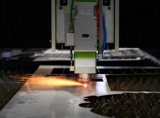
Laser Cutting
Laser cutting uses a high-powered laser beam to melt or vaporize the material, achieving precise cuts. This method is highly accurate and flexible.
Plasma Cutting
Plasma cutting uses a high-temperature, high-speed plasma arc to melt metal and blow it away. It is suitable for cutting thicker conductive metals like carbon steel and stainless steel, though it doesn't provide the same precision or finish quality as laser cutting.
Waterjet Cutting
Waterjet cutting uses ultra-high-pressure water mixed with abrasive materials to erode and cut through metals. Its main advantage is that it’s a cold-cut process, avoiding thermal effects. It can cut a variety of materials, including metals, stone, glass, and composites, but is slower and more costly.
Punching
Punching employs molds and press machines to create holes or blanks in a sheet metal. Ideal for high-volume production of simple parts, but it comes with high tooling costs and limited flexibility.
Shearing
Shearing uses shears to cut along straight lines. This process is best suited for making simple straight edges.
2. Forming
Forming involves shaping flat sheets into three-dimensional forms using external forces.
Bending
The most common forming process, using a press brake and die to bend sheet metal into a specified angle.
Stamping
Stamping utilizes molds and presses to perform operations like punching, drawing, flanging, and embossing. This method is ideal for mass production.
Rolling
Rolling is a process where metal sheets are rolled into cylindrical or curved shapes, commonly used for creating pipes, tanks, and similar objects.
Deep Drawing
Deep drawing is a specialized stamping process where flat sheets are formed into deep, hollow parts like automotive fuel tanks and stainless steel sinks.
3. Joining & Assembly
This category involves the joining of multiple sheet metal parts into a final assembly.
Welding
The most common method, including techniques like TIG welding, MIG welding, and spot welding, to create permanent bonds between parts.
Riveting
Riveting uses rivets for mechanical fastening, offering a detachable or semi-permanent bond.
Threaded Fasteners
Screws and bolts provide an easily removable connection.
Adhesive Bonding
Adhesive bonding uses industrial glues to join parts together.
4. Finishing
Finishing processes are applied to the surface of the part to meet requirements for corrosion resistance, appearance, or specific functions.
Painting/Spraying
Painting or spraying applies a coating for a smooth finish.
Plating
Techniques like galvanizing, chrome plating, and nickel plating add a metallic coating to a part.
Anodizing
Anodizing primarily applies to aluminum alloys, increasing corrosion resistance and surface hardness.
Screen Printing/Laser Marking
Screen printing or laser marking adds markings, logos, or patterns to a surface.
Understanding Sheet Metal Tolerances
Precision refers to how closely the final result matches the desired target, whereas tolerance is the allowable range of variation in dimensions.
Why Tolerances Matter in Sheet Metal Fabrication
- Manufacturability: Tolerances define what is acceptable in terms of variation.
- Interchangeability: Tolerances ensure that parts from different batches or machines fit together seamlessly.
- Cost Control: Stricter tolerances require higher precision equipment and longer inspection times, increasing production costs.
Factors Affecting Precision
Equipment capability, tooling condition, material properties, process selection, operator skills, and fixturing & positioning all influence the final precision.
Typical Tolerances for Various Processes
1. Cutting Tolerances
- Laser Cutting: ±0.1mm or smaller for thin sheets and small parts.
- Plasma Cutting: ±0.5mm to ±1.5mm depending on material thickness.
- Waterjet Cutting: ±0.1mm to ±0.2mm.
2. Bending Tolerances
- Bending angle tolerance: ±1°, can be reduced to ±0.5° with advanced equipment.
- Bending size tolerance: After the first bend: ±0.3mm; after multiple bends: ±1mm or more.
3. Punching/Tapping Tolerances
- Hole position tolerance: ±0.1mm (for CNC turret punches).
- Hole diameter tolerance: ±0.05mm to ±0.1mm.
How to Mark Tolerances on Design Drawings
Use general tolerances in the title block or notes and critical tolerances for key dimensions that affect function or assembly.
General Tolerances:
These are usually indicated in the title block or annotations on the drawing, such as:Dimensions in mm.
General Tolerances: ±0.5 for linear dimensions, ±1° for angular dimensions.
This means that all dimensions not individually specified with tolerances will follow these standard values.
Critical Tolerances:
For dimensions that have assembly, functional, or aesthetic requirements, stricter tolerances must be indicated directly on the dimension itself.
For example: A hole intended for a screw might be marked as Ø5.2 +0.1/0 (indicating that the hole diameter should be between 5.2mm and 5.3mm).
For example: The center distance between two holes that need precise alignment should be marked as 100 ±0.2.
Summary & Recommendations
- Tolerance is an essential part of sheet metal fabrication.
- Communication with the manufacturer about precision requirements is crucial.
- Balance is important: avoid overly strict tolerances unless absolutely necessary.