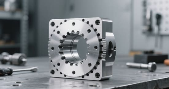
What is CNC Drilling?
Computer Numerical Control (CNC) drilling is a machining method where pre-programmed G-code directs the drill’s position and cutting parameters. The machine executes commands generated from CAD/CAM designs to create precise holes in materials.
Core Advantages
- High Accuracy: Standard tolerance ±0.05 mm; high-precision tolerance up to ±0.01 mm.
- Consistency: Whether drilling 10 holes or 1,000, positional deviation is minimal.
- Automated Production: Minimizes human intervention and reduces the chance of error.
- Versatility: Suitable for metals (aluminum, stainless steel, titanium), plastics (POM, PEEK), and composites (CFRP, G10).
Working Principle (Example):
Design holes and tolerances in CAD.
Generate G-code via CAM software to control the machine.
Drill rotates and cuts the material.
Cooling and chip removal systems operate concurrently to ensure hole quality and tool life.
2. Comparison of Drilling Types: From Through-Holes to Deep-Hole Applications
| Type | Description | Application | Notes |
|---|---|---|---|
| Through-Hole | A hole that passes completely through the material. | Bolt connections; ventilation or fluid channels. | Remove burrs on the exit side; consider adding back-chamfer. |
| Blind Hole | A hole with a fixed depth, not penetrating the other side. | Threaded holes; locating features. | Control depth precisely; prevent end-wear on the tool. |
| Deep Hole (depth > diameter × 10) | Long, narrow holes. | Hydraulic cylinder bodies; mold cooling channels. | Difficult chip evacuation; high tool heat. Tech Tip: use peck drilling, high-pressure coolant for chip flushing. |
| Countersink / Counterbore | Enlarged or flared entry to allow fastener head to sit flush or recessed. | Aircraft skins; mechanical assemblies. | Match countersink angle to fastener specs. |
3. CNC Drilling Workflow: From Design to Completion
Design Phase
Annotate hole diameter, tolerance, and position in CAD.
Avoid non-standard diameters to minimize tool changes.
Programming Phase (CAM)
Optimize drilling order to reduce tool movement/change.
Set feed rate, spindle speed, and coolant method.
Tool Selection
Metals: carbide drills (longer life, higher rigidity)
Plastics: high-speed steel drills (reduce cracking risk)
Test Run & First-Part Inspection
Check diameter and positional tolerances.
Adjust parameters to meet specifications.
Batch Processing
Maintain effective cooling and chip evacuation.
Monitor tool wear and replace as needed.
Final Inspection
Use CMM (Coordinate Measuring Machine) to check full dimensions.
Inspect surface finish and burrs.
4. Key Parameters: Speed, Feed, and Cooling Strategy
Spindle Speed (RPM):
RPM=Vc×1000/π×D
- Aluminum: 80–200 m/min
- Stainless steel: 20–50 m/min
- Plastics: 150–300 m/min
Feed Rate:
Small holes (≤3 mm): 0.01–0.05 mm/rev
Medium holes (3–10 mm): 0.05–0.15 mm/rev
Large holes (>10 mm): 0.15–0.30 mm/rev
Cooling Strategy:
Metals: use water-based coolant, high-pressure for chip evacuation
Plastics: air cooling to prevent expansion or deformation
Deep holes: high-pressure coolant + chip-flushing drill

5. Drill-Bit Geometry & Its Effects
Point Angle:
118°: for soft materials (aluminum, plastics)
135°: for hard materials (stainless steel, titanium)
Helix Angle:
High (35°–40°): good for chip removal (aluminum, copper)
Low (15°–25°): higher rigidity (steel, stainless steel)
Surface Coating:
- TiN (Titanium Nitride): general anti-wear
- TiAlN (Titanium Aluminum Nitride): high-temperature resistance
- DLC (Diamond-like Carbon): ideal for carbon fiber and plastic
6. Real-World Examples & Industry Best Practices
Aerospace:
Thousands of high-precision countersinks for aircraft skin assemblies; auto tool-changing boosts efficiency.
Automotive:
Deep oil and coolant channels in engine blocks; high-pressure coolant avoids hole surface burning.
Electronics:
PCB micro-vias (0.2–0.3 mm) require spindle speeds ≥ 60,000 RPM.
Best Practices:
Validate parameters with pre-production samples.
Use peck drilling for deep-hole operations to avoid tool breakage.
Ensure tool holder runout ≤ 0.01 mm.
Regularly clear chips to avoid secondary damage to hole walls.
Four FAQ Questions
What exactly is CNC drilling and why is it preferred over manual drilling?
Explain CNC drilling as a computer-controlled process offering superior precision, consistency, and automation compared to manual methods.
Which types of holes can CNC drilling handle and what should I be aware of for each?
Describe through-holes, blind holes, deep holes, countersinks/counterbores, with application contexts and important considerations.
What are the key parameters (speed, feed, cooling) in CNC drilling and how do they vary by material?
Provide speed and feed formulas and ranges for metals vs plastics, plus cooling strategy recommendations.
How do drill bit geometry and coatings affect performance and material compatibility?
Clarify the choice of point angle, helix angle, and surface coating based on material type.


