الدليل النهائي لمعالجة الخيوط 3 / 8-16 UNC
في مجال التصنيع الصناعي ، تخدم الخيوط كمكونات أساسية لتطبيقات الاتصال والتثبيت والختم. تحدد دقة معالجة الخيوط بشكل مباشر استقرار المعدات والسلامة وعمر الخدمة. من بين معايير الخيوط المختلفة ، ظهرت خيط 3/8-16 UNC كمعيار عالمي عبر صناعات التصنيع الميكانيكي وصناعة السيارات والفضاء والأجهزة الطبية بسبب توازنها الأمثل بين القدرة على التكيف مع القوة والتوافق العالمي والبنية التحتية الناضجة لسلسلة التوريد.
من تثبيت قوس المعدات الصغيرة إلى تطبيقات ختم غطاء المحرك الحرجة ، يظهر خيط 3/8-16 UNC تنوعاً ملحوظاً. ومع ذلك ، تنطوي معالجة هذا الخيط على تعقيد أكبر بكثير من مجرد اختيار الصنبور وحفر ثقب. يمكن أن يؤدي حجم الحفر غير الصحيح إلى تجريد الخيوط أو كسر الصنبور ، في حين أن إهمال خصائص المواد قد يسبب ارتداء أداة سريع في الفولاذ المقاوم للصدأ أو التشقق في مكونات البلاستيك بسبب المشاركة المفرطة.
هذا الدليل الشامل يفكك بشكل منهجي منطق التصنيع وراء خيوط 3/8-16 UNC عبر سبعة أبعاد حرجة: الفهم الأساسي، وحسابات الأبعاد، وتوافق المواد، واختيار الأدوات، وتنفيذ العملية، وفحص الجودة، وبروتوكولات الصيانة. وبالإضافة إلى التطبيقات القياسية، نستكشف حلول متخصصة للمواد الصعبة، والتجهيز بالثقوب العميقة، وإدراجات الملفات الحلفية، وتمكين المهندسين والآليين وفرق المشتريات مع معرفة التصنيع المنهجية.
القسم 1: الفهم الأساسي لخيوط UNC 3/8-16: تعريفات المعلمات والأهمية الصناعية
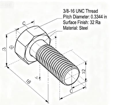
1.1 تحليل المعلمات الأساسية لخيوط 3 / 8-16 UNC
قطر رئيسي: 3/8 بوصة (حوالي 9.525 مم) ، تمثل أقصى قطر لقمة الخيط ، وتخدم كقطر اسمي ومعيار مطابقة للمثبتات.
خيوط لكل بوصة (TPI): 16 خيوط لكل بوصة، ما يعادل 1/16 بوصة (حوالي 1.5875 مم). تتميز الخيوط الخشنة (UNC) بأقل عدد من TPI وملفات الخيوط الأوسع ، مما يوفر مقاومة متفوقة للتجريد - مفيدة بشكل خاص في المواد الناعمة مثل الألومنيوم والنحاس حيث قد يسبب الاهتزاز أو التحميل تشوه الخيوط.
نموذج موضوع: يستخدم زاوية خيط متناظرة 60 درجة ، مع ارتفاع الخيط يمثل نصف الفرق بين القطر الرئيسي والصغير. يتميز خيط UNC القياسي 3/8-16 بقطر طفيف يبلغ حوالي 0.3125 بوصة (5/16 بوصة) ، مما يشكل الأساس لاختيار حجم الحفر القياسي.
فئة مناسبة: يستخدم عادة تصنيفات 2B (الخيوط الداخلية) و 2A (الخيوط الخارجية) ، مما يمثل دقة تناسب متوسطة توازن بين سهولة التجميع وأداء الختم. قد تتطلب التطبيقات عالية الدقة (الطيران) تصنيفات 3B / 3A مع متطلبات تسامح أكثر صرامة لقطر الملعب وزاوية الخيط.
1.2 الهيمنة الصناعية لخيوط 3/8-16 UNC
ينبع التبني الواسع النطاق لخيوط 3/8-16 UNC عبر صناعات متعددة من توازنها الأمثل بين القوة وصعوبة التصنيع وفعالية التكلفة:
قوة التكيف: يوفر ملف تعريف الخيط الخشن مساحة تحمل الحمل الكبيرة ، مع قطر 3/8 بوصة قادر على تحمل قوة الشد 500-800 ميجا باس (تعتمد على المادة) ، مما يلبي متطلبات تثبيت المعدات الخفيفة وتحميل المكونات الهيكلية المتوسطة (قوسين المحركات الصناعية).
التوافق مع التصنيع: المزيج من الملعب والقطر في 3/8-16 خيوط يقلل من مشاكل مثل كسر الصنبور وتشويه الخيط عبر عمليات التحول بالعدد الآلي والطحن والنقط اليدوي ، مع متطلبات دقة معدات معتدلة تمكن من التصنيع المستقر حتى في ورش العمل الصغيرة والمتوسطة.
نضج سلسلة التوريد: الصنابير المقابلة والمحفرات والمثبتات (المسامير والمكسرات) هي سلع منتجة بشكل كبير بتكاليف شراء منخفضة وأوقات قيادة قصيرة ، مما يزيل الحاجة إلى أدوات متخصصة ويقلل من حواجز التصنيع.
القسم 2: الحسابات الأساسية لأحجام حفرة الصنبور 3/8-16: من النظرية إلى الممارسة
يمثل قياس ثقب ما قبل الحفر الخطوة الأولى الحاسمة في معالجة الخيوط 3/8-16 - تؤدي الثقوب الكبيرة الحجم إلى عدم كفاية مشاركة الخيوط وتجريدها ، في حين تزيد الثقوب القليلة الحجم من أحمال القطع ومخاطر كسر الصنبور. يستمد الحجم الصحيح من الحسابات الهندسية بناءً على نسب مشاركة الخيط بدلاً من التقديرات التجريبية.
2.1 مبادئ حساب حجم الحفر: مشاركة الخيط كهدف أساسي
تحدد نسبة مشاركة الخيط منطقة الاتصال الفعلية بين الخيوط الداخلية (الثقب) والخارجية (المسمار) بالنسبة لمساحة الاتصال الكلية النظرية ، والتي تعمل كمحدد حاسم لقوة الخيط. يحدد توافق الآراء في الصناعة 60٪ - 75٪ كمجموعة المشاركة المثلى:
أقل من 60%: عدم كفاية مساحة الاتصال يزيد من خطر تخفيف المسامير أو سحبها ، وخاصة في البيئات الاهتزازية (هيكل السيارات).
فوق 75%: يزيد حجم القطع المفرط بشكل كبير من عزم الدوران في الصنبور ، مما يسرع التآكل أو الكسر مع تقليل كفاءة التصنيع.
استنادا إلى هذه المبادئ، تتبع حسابات حجم الحفر الموحدة (UNC / UNF) الصيغة الموحدة:
حجم ما قبل الحفر = قطر رئيسي - (1 ÷ خيوط لكل بوصة)
2.2 حساب الحجم القياسي والتحقق من 3/8-16 UNC
تطبيق المعلمات 3/8-16 على الصيغة:
قطر رئيسي = 3/8 بوصة = 0.375 بوصة
1 ÷ TPI = 1 ÷ 16 = 0.0625 بوصة
حجم ما قبل الحفر = 0.375 - 0.0625 = 0.3125 بوصة = 5/16 بوصة
يتوافق هذا البعد مع حفرة الحرف F في أنظمة الحجم الإمبراطورية (حيث تتميز الحفرات المحددة بالحرف بأقطار محددة ، مع قياس حفرة F بدقة 0.3125 بوصة) ، وهي الخيار الرئيسي لتطبيقات الخيوط العامة 3 / 8-16. عبر الصلب منخفض الكربون أو الألومنيوم أو المواد النحاسية ، يحقق الحفر 5/16 بوصة حوالي 70٪ من المشاركة ، مما يوازن القوة مع قابلية التصنيع.
2.3 تعديلات الحجم لمتطلبات المشاركة المختلفة
تتطلب التصنيع العملي تعديلات حجم الحفر بناء على متطلبات صلابة المواد وقوتها ، مع انحرافات مسيطرة عليها عن القيم القياسية:
| متطلبات المشاركة | سيناريو التطبيق | حجم الحفر (بوصة) | معادل عشري | أمثلة مادية |
|---|---|---|---|---|
| 60%-65% | المواد الصلبة، النقر على ثقب عميق | 21/64 | 0.3281 | الفولاذ المقاوم للصدأ 304 ، التيتانيوم TC4 |
| 70%-75% | التطبيقات العامة، المواد المتوسطة الصلبة | 5/16 (حفرة F) | 0.3125 | منخفض الكربون الصلب Q235، الألومنيوم 6061 |
| 80%-85% | المواد الناعمة، متطلبات القوة العالية | 19/64 | 0.2969 | النحاس H62، ABS البلاستيك، البولي بروبيلين |
ملاحظة مهمة: يجب ألا تتجاوز نطاقات الضبط ± 0.0156 بوصة (حوالي 0.4 مم) ، لأن الانحرافات الأكبر قد تسبب في تجاوز معايير الخيط لمواصفات التسامح 2B / 3B. على سبيل المثال، استخدام 17/64 بوصة (0.2656 بوصة) الحفرات للمكونات البلاستيكية قد تزيد من المشاركة ولكن المخاطر كسر الصنبور بسبب ضغط المواد.
القسم 3: تأثيرات خصائص المواد على اختيار الصنبور والحفر 3/8-16
خصائص المواد - الصلابة، اللونة، الموصلية الحرارية - تحدد مباشرة المزيج المثالي من أحجام الحفر وأنواع الصنبور ومعلمات القطع. تتطلب مواصفات الخيوط المتطابقة 3/8-16 أساليب معالجة مختلفة تمامًا للفولاذ المقاوم للصدأ مقابل المواد البلاستيكية ، حيث يكون إهمال خصائص المواد السبب الرئيسي لفشل المعالجة.
3.1 المواد الناعمة (صلابة ≤150 HB): التحكم في الشريحة وإدارة المشاركة
وتشكل المواد الناعمة مثل الألومنيوم 6061 والنحاس H62 والبلاستيك ABS والبولي بروبيلين تحديات في التصنيع المتصلة بالالتصاق بالرقائق وتشوه المواد، مما يتطلب " تدريبات أصغر + صنابير مضادة للالتصاق" الحلول:
اختيار حجم الحفر: تفضل تدريبات 19/64 بوصة (0.2969 بوصة) لتحقيق حوالي 80٪ من المشاركة - المواد الناعمة تتعرض لتشوه الخيط تحت الضغط ، مع ارتفاع نسب المشاركة التي تحسن مقاومة الشريط. بالنسبة للبلاستيك المعرض للصدوق (PVC) ، تقلل الحفرات القياسية 5/16 بوصة من الضغط الشعاعي أثناء النقر.
أنواع النقر: صنابير نقطة دوامة موصى بها أو صنابير شكل لفة:
- صنابير نقطة دوامة: ميزة قنوات طرد الشريحة الموجهة للأمام (مثالية للثقوب) ، ومنع تراكم الشريحة في أشكال الخيط.
- لفة شكل الصنابير: استخدم تشكيل الخيط بدون رقاقة من خلال تشوه المواد البلاستيكية ، مناسبة للألومنيوم والنحاس المرنة مع التشطيب السطحي المتفوق (Ra≤0.8μm) ولا مخاوف إخلاء الشريحة (الثقوب العمياء).
معايير القطع: 800-1500 دورة في الدقيقة سرعات المغزل ، ومعدلات التغذية = دورة في الدقيقة × الملعب (على سبيل المثال ، 1000 دورة في الدقيقة × 0.0625 بوصة / دورة = 62.5 بوصة / دقيقة) ؛ الزيوت المعدنية الخفيفة أو سوائل القطع الاصطناعية المفضلة على الزيوت عالية اللزوجة (خطر الالتصاق الشريحة).
3.2 المواد المتوسطة الصلبة (150-300 HB): التوازن بين قوى القطع وعمر الأداة
المواد المتوسطة الصلبة، بما فيها الفولاذ المنخفض الكربون Q235، والفولاذ المقاوم للصدأ 304، والحديد الزهري HT200، توفر مقاومة معتدلة للقطع مع اتجاهات لتشكيل الحواف المتراكمة، مما يتطلب " تدريبات قياسية + صنابير مغلفة " للتوازن بين الكفاءة وطول العمر:
اختيار حجم الحفر: تمثل حفرة 5/16 بوصة (F) الحل الأمثل ، مع مشاركة 70٪ تضمن القوة دون تحميل الصنبور المفرط. بالنسبة للفولاذ المقاوم للصدأ 304 (موصلة حرارية ضعيفة ودرجات حرارة القطع العالية) ، فكر في تدريبات 21/64 بوصة لتقليل حجم القطع ودرجات حرارة الصنبور.
أنواع النقر: إعطاء الأولوية لصنابير البنوت الدوارة المغطاة بـ TiN:
- صنابير فلوت دوامة: البنوتات ذات الزاوية الصاعدة تخلي الشرائح من قاع الثقب الأعمى ، مما يمنع كسر الصنبور من ضغط الشرائح.
- طلاء TiN: يوفر صلابة HV2000 مقاومة استثنائية للتآكل ، مما يقلل من الاحتكاك مع الفولاذ المقاوم للصدأ ويمدد عمر الأداة 2-3 × مقارنة بأدوات HSS القياسية.
معايير القطع: 500-800 دورة في الدقيقة (المدى السفلي للصدأ ، العلوي للفولاذ الخفيف) ، معدلات التغذية المتزامنة ؛ توفر سوائل قطع الزيت القابلة للذوبان (تخفيف 5٪ -10٪) كل من التبريد (تبديد الحرارة) والتزييت (منع الحافة المتراكمة).
3.3 المواد الصلبة (≥300 HB): تقليل الحمل والإدارة الحرارية
وتشكل المواد الصلبة مثل الفولاذ المقاوم للصدأ 316 المعالج بالمحلول والتيتانيوم TC4 وفولاذ الأدوات Cr12 تحديات تتمثل في ارتفاع الصلابة وارتفاع درجات حرارة القطع وسرعة التخلص من الصنبور، مما يتطلب " تدريبات أكبر + صنابير الكربيد" للحد من الحمل:
اختيار حجم الحفر: الاستخدام الإلزامي لمدربات 21/64 بوصة (0.3281 بوصة) الحفاظ على 60٪ -65٪ من المشاركة - المواد الصلبة تولد قوى قطع أعلى 3-5 أضعاف من المواد الناعمة ، مع المشاركة المفرطة تسريع ارتداء قمة الصنبور وانحراف قطر الملعب.
أنواع النقر: كوبالت فولاذ عالية السرعة (HSS-E) أو كربيد التنغستن (WC-Co) الصنابير:
- صنابير HSS-E: يوفر محتوى الكوبالت 5٪ -8٪ صلابة ساخنة عالية (HRC60 عند 600 درجة مئوية) ، مناسبة لمعالجة الفولاذ المقاوم للصدأ 316 الدفعة.
- صنابير الكربيد: تقدم صلابة HRC70 + مقاومة استثنائية للتآكل ولكن تتطلب نقطة صلبة (مزامنة دقيقة لتغذية المغزل) لمنع الكسر الهش من الاهتزاز.
معايير القطع: 300-500 دورة في الدقيقة (≤300 دورة في الدقيقة للتيتانيوم) ، 10٪ -15٪ معدلات التغذية المنخفضة (على سبيل المثال ، 300 دورة في الدقيقة × 0.0625 بوصة / دورة = 18.75 بوصة / دقيقة) ؛ تشكل الزيوت النظيفة ذات الضغط الشديد (إضافات الكبريت / الفوسفور) أفلام التشحيم تحت درجات الحرارة العالية ، مما يقلل من ارتداء الصنبور.
3.4 المواد المركبة (CFRP، GFRP): منع التسرب والصيانة الدقيقة
وتشكل المواد البلاستيكية المعززة بألياف الكربون والمركبات البلاستيكية المعززة بألياف الزجاج تحديات في التصنيع المتمثلة في كسر الألياف وتفكيك المصفوفة، مما يتطلب " أدوات متخصصة + سرعات منخفضة":
اختيار حجم الحفر: تقريبا القياسية 5/16 بوصة، الموصى بها 0.310 بوصة (الحفرات المخصصة) - تسبب الأنيسوتروبيا المركبة سحب الألياف أثناء التخييط، مع الحفرات الكبيرة الحجم تفاقم التسليط والحفرات القليلة الحجم ضغط الألياف.
أنواع النقر: الصنابير المغطاة بالماس أو كربيد التنغستن مع حواف القطع المحسنة (تجنب الحواف الحادة التي تقطع الألياف) ؛ يدوي أو منخفض السرعة CNC النقر المفضل لتقليل تلف الألياف الناجمة عن الاهتزاز.
تفاصيل العملية: تنفيذ 45 درجة شامفرز (عمق 0.5 مم) قبل النقر لمنع الحافة delamination؛ التشحيمات القائمة على الكحول (غير التآكل، متوافقة مع الراتنج) الموصى بها على السوائل القائمة على الزيت (خطر اختراق المصفوفة).
القسم 4: حلول التصنيع المتخصصة لإدراج 3 / 8-16 لفائف سلسلة
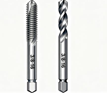
عند معالجة 3/8-16 خيوط في مواد ناعمة (الألومنيوم أو البلاستيك) أو مكونات ذات جدران رقيقة ، قد تتلف أشكال الخيوط تحت التفكيك المتكرر أو التحميل العالي - تثبيت إدراجات لفائف حلوية (إدراجات خيوطية) يعزز موثوقية الاتصال من خلال خيوط مضمنة عالية القوة. تختلف هذه العملية بشكل أساسي عن النقر المباشر ، مع التركيز على التوافق مع إدراج أبعاد الخيط الخارجي.
4.1 مبادئ وأنواع تشغيل لفائف مروحية
وتشكل الملفات المروحية أكمام خيطية شبيهة بالربيع مصنوعة من الفولاذ المقاوم للصدأ أو سبيكات النحاس، ومثبتة لتوفير " خيوط خارجية" إشراك ثقوب المكونات و " خيوط داخلية" التزاوج مع المسامير - تضمين بشكل فعال أشكال الخيط عالية القوة في المواد الناعمة. وتشمل المتغيرات الشائعة:
لفائف التشغيل الحر: تفتقر الخيوط الداخلية إلى ميزات القفل ، مناسبة لتطبيقات الحمل الثابت (تثبيت غلاف المعدات).
لفائف القفل الذاتي: تتضمن الخيوط الداخلية 1-2 خيوط مشوهة تخلق تداخل يناسب المسامير ، مما يوفر مقاومة للاهتزاز (ملحقات محركات السيارات).
4.2 Processing Steps and Dimensional Requirements for 3/8-16 Helical Coils
Helical coil installation follows four critical steps—drilling, tapping, installation, and tang breakoff—each requiring precise dimensional control:
Pre-Drilling: Critical dimension involves hole size compatibility with insert external threads. Standard 3/8-16 helical coils feature external thread specifications of "3/8-16 STI" (Screw Thread Insert), requiring 25/64-inch (0.3906 inch) pre-drill sizes—0.0781 inches larger than direct tapping's 5/16-inch dimension, providing clearance for insert external threads to prevent wall cracking during installation.
ملاحظة: Insert brands may feature slight dimensional variations—always consult manufacturer drilling specifications (e.g., specific 3/8-16 self-locking inserts may require 0.391 inch ±0.002 inch holes).
Tapping: Mandatory use of STI-specific taps featuring different thread forms than standard 3/8-16 taps—STI taps exhibit greater thread height with tighter pitch tolerances, ensuring complete insert external thread engagement with hole walls. Tap depth should exceed insert length by 1-2 pitches (e.g., 0.5-inch insert requires 0.5 + 0.0625×2 = 0.625 inch depth), preventing incomplete insert seating.
Insert Installation: Utilize dedicated installation tools (guide mandrels and sleeves) to thread inserts into prepared holes until installation tangs flush with component surfaces; maintain 20-30 N·m installation torque (upper range stainless inserts, lower copper inserts)—excessive torque causes distortion, insufficient torque risks loosening.
Tang Breakoff: Free-running inserts require tang removal using breakoff tools (pre-weakened fracture points); self-locking variants typically lack tangs, ready for immediate use.
4.3 Common Helical Coil Machining Errors and Prevention
Error 1: Using standard 3/8-16 taps for STI holes.
النتيجة: Insert external threads fail to engage properly, causing loosening or complete pull-out.
Error 2: Selecting drill sizes based on standard tapping (5/16 inch).
النتيجة: Inserts cannot thread into holes, with forced installation cracking hole walls and scrapping components.
Error 3: Neglecting tang breakoff after installation.
النتيجة: Tangs interfere with bolt installation, preventing proper seating and compromising connection strength.
Section 5: High-Precision 3/8-16 Thread Machining in CNC Environments
CNC machining represents the primary method for 3/8-16 thread batch production, offering superior precision and consistency through optimized parameters, fixture design, and error compensation—particularly critical for high-precision applications (aerospace components with ≤0.02 mm thread position tolerances).
5.1 Parameter Optimization: Speed, Feed, and Depth Synchronization
CNC tapping parameters require adjustment based on material, tap type, and hole configuration (through/blind), with core emphasis on maintaining perfect spindle-feed synchronization (rigid tapping) to prevent pitch errors:
| نوع المواد | Tap Type | RPM | Feed Rate (ipm) | Tap Depth (inches) | Hole Type |
|---|---|---|---|---|---|
| Aluminum 6061 | Form Tap | 1200 | 75 (1200×0.0625) | Thread length + 0.125 | Blind |
| Mild Steel Q235 | TiN Plug Tap | 800 | 50 (800×0.0625) | Thread length + 0.0625 | Through |
| Stainless 304 | HSS-E Spiral | 500 | 31.25 (500×0.0625) | Thread length + 0.125 | Blind |
| التيتانيوم TC4 | Carbide Tap | 300 | 18.75 (300×0.0625) | Thread length + 0.1875 | Blind |
Depth Control Techniques: Blind holes require chip clearance space—depth = effective thread length + 1.5×pitch (e.g., 0.5 inch length → 0.5 + 1.5×0.0625 = 0.59375 inches); through holes should extend 0.5×pitch beyond part backsides ensuring complete thread formation.
5.2 Tapping Method Selection: Rigid vs. Flexible Tapping
CNC tapping employs two primary methodologies selected according to machine precision and hole depth requirements:
Rigid Tapping: CNC system synchronizes spindle rotation with axis movement in real-time (angular position precisely matching linear travel), eliminating need for floating holders and providing superior accuracy (pitch error ≤0.001 inch), ideal for high-precision components (medical devices) and shallow holes (depth ≤2×diameter).
Requirements: Machine must support rigid tapping functionality with rigid tool holders (ER collets) preventing holder movement causing synchronization errors.
Flexible Tapping: Floating holders compensate for minor spindle-feed mismatches, suitable for deep holes (depth >3×diameter) and less rigid machines (older mills).
ملاحظة: Float should not exceed 0.1 mm to prevent pitch diameter deviations; flexible tapping accuracy falls short of rigid methods, unsuitable for 3B class threads.
5.3 Fixturing and Positioning Accuracy Control
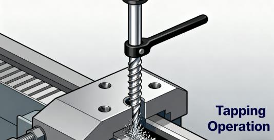
Thread position and perpendicularity represent critical CNC machining metrics (e.g., automotive transmission cover threads requiring ≤0.01 mm perpendicularity), achieved through fixture optimization:
Location Datum: Prioritize component design datums (planes, holes) as reference surfaces preventing errors from datum misalignment—e.g., bracket 3/8-16 threads should reference mounting surfaces with ≤0.005 mm flatness.
Clamping Methods: Soft materials (aluminum) utilize soft jaws preventing surface damage; hard materials (stainless) employ hydraulic fixtures ensuring uniform clamping force (force = material yield strength × contact area ×1.2), preventing workpiece displacement during machining.
Pre-Drill Accuracy: Pre-drill hole tolerances should maintain ±0.003 inches with perpendicularity ≤0.005 mm—consider drill-reamer sequences improving hole quality before tapping operations.
Section 6: Cutting Fluid Critical Functions and Selection for 3/8-16 Thread Machining
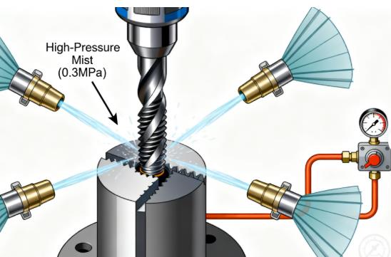
Cutting fluids serve as "invisible tools" in 3/8-16 thread machining—reducing friction, controlling temperatures, improving thread quality, and extending tool life. Particularly with hard materials, omitting cutting fluids may reduce tap life by over 50%.
6.1 Four Core Functions of Cutting Fluids
Lubrication: Forms oil films between taps and workpieces reducing friction coefficients (from 0.3 to below 0.1), decreasing tapping torque and preventing tap crest wear.
التبريد: Dissipates heat from cutting zones (tapping stainless steel may exceed 600°C), preventing tap softening (HSS softening temperature ≈550°C) and workpiece thermal distortion.
Chip Evacuation: Fluid flow removes chips from thread holes preventing chip accumulation between thread forms causing distortion or tap breakage.
Corrosion Prevention: Forms protective films on workpieces and tools preventing post-machining rust (humid environments) and tool corrosion.
6.2 Cutting Fluid Selection Guide for 3/8-16 Threading
Different materials require specific lubrication and cooling characteristics:
| نوع المواد | Primary Need | Recommended Fluid | Key Specifications | Usage Notes |
|---|---|---|---|---|
| Aluminum/Copper | Anti-adhesion, corrosion prevention | Synthetic fluids (pH8-9) | Chloride ≤50 ppm (aluminum protection) | Maintain concentration (5%-8%), avoid over-dilution |
| Mild Steel | Cooling, rust prevention | Soluble oils (10% dilution) | Rust protection ≥7 days (indoor) | Avoid hard water mixing (scum formation) |
| الفولاذ المقاوم للصدأ | EP lubrication, heat resistance | Neat oils (sulfur/phosphorus) | Flash point ≥180°C (fire safety) | Post-cleaning required (oil film removal) |
| سبيكات التيتانيوم | High-temp lubrication, oxidation prevention | EP synthetic fluids | Antioxidants ≥5% | Filtration required (20μm), contamination control |
| Plastics/Composites | Delamination prevention, non-corrosive | Alcohol-based or dry lubricants | Non-resin dissolving | Prohibit oil-based fluids (matrix penetration) |
6.3 Cutting Fluid Application and Maintenance Techniques
Concentration Control: Soluble oils and synthetic fluids require precise dilution—excessive concentration increases viscosity impairing chip evacuation, while insufficient concentration reduces lubrication and corrosion protection. Use refractometers for weekly concentration checks.
Filtration and Cleanliness: Implement magnetic separators (ferrous chips) and paper filters (contaminants) preventing chip accumulation in fluids causing tap wear; monthly sump cleaning removes sediment preventing bacterial growth (humid environments).
Replacement Cycles: Standard fluids require 3-6 month replacement, extreme-pressure fluids (stainless, titanium) 6-12 months; immediately replace fluids showing odor, discoloration, or oil separation signs.
Section 7: 3/8-16 Thread Quality Inspection and Defect Resolution Strategies
Post-machining thread quality requires comprehensive verification preventing defective threads entering assembly processes, with dedicated solutions addressing common issues (stripping, burrs) reducing scrap rates.
7.1 Core Inspection Metrics and Tools
Dimensional Accuracy: Includes pitch diameter, major diameter, and minor diameter compliance with 2B or 3B class tolerances (3/8-16 UNC 2B internal thread pitch diameter tolerance: 0.3340-0.3420 inches).
Inspection Tools: Thread micrometers (pitch diameter, 0.001 inch accuracy), thread plug gages (GO/NO-GO gages—GO must pass, NO-GO must not pass).
Position and Perpendicularity: Position compliance with drawing specifications (±0.02 mm), perpendicularity ≤0.01 mm/10 mm.
Inspection Tools: CMM (batch inspection, 0.0005 inch accuracy), perpendicularity gages (individual part verification, high efficiency).
Surface Quality: Complete thread forms without chipping, burrs, or scratches, surface roughness Ra≤1.6μm (general) or Ra≤0.8μm (high-precision).
Inspection Tools: Surface roughness testers (crest/root measurements), metallurgical microscopes (thread form integrity, micro-defect detection).
Strength Verification: Pull-out testing determines thread resistance—install matching bolts in 3/8-16 threads applying axial tension until failure, recording maximum force (e.g., aluminum 6061 threads should withstand ≥15 kN).
7.2 Common 3/8-16 Thread Defects and Solutions
| Defect Type | Root Causes | Corrective Actions |
|---|---|---|
| Stripped Threads | 1. Oversized drill, <60% engagement; 2. Insufficient material strength | 1. Smaller drill (5/16→19/64); 2. Install helical coils |
| Tap Breakage | 1. Undersized drill, excessive load; 2. Poor chip evacuation | 1. Larger drill (5/16→21/64); 2. Spiral flute taps + high-pressure coolant |
| Thread Burrs | 1. Dull tap, poor edge sharpness; 2. Insufficient coolant | 1. Sharpen or replace tap; 2. Increase coolant pressure (10-15 bar) |
| Pitch Errors | 1. CNC spindle-feed mismatch; 2. Tap pitch deviation | 1. Calibrate rigid tapping parameters; 2. Use ANSI-compliant taps |
| Pitch Diameter Deviation | 1. Tap wear; 2. Excessive tapping torque | 1. Replace tap; 2. Reduce torque (30→25 N·m) |
| Plastic Thread Cracking | 1. Undersized drill, high compressive stress; 2. Excessive speed | 1. Standard 5/16-inch drill; 2. Reduce speed (300-500 RPM) |
7.3 Quality Control Procedures for Batch Production
Ensuring 3/8-16 thread consistency across production batches requires implementing "first-piece - process - last-piece" inspection protocols:
First-Piece Inspection: Machine 1-3 pieces before batch production, complete dimensional, positional, and surface quality verification, confirming parameter validity before full-scale production.
Process Sampling: Inspect 1 piece per 50 units, focusing on pitch diameter and position, immediately stopping for adjustment if deviations occur (tap calibration, parameter optimization).
Last-Piece Inspection: Verify final piece upon batch completion, comparing with first-piece data confirming tool wear within acceptable limits (tap wear ≤0.01 mm).
SPC Statistical Process Control: Utilize SPC software recording thread dimension data per batch, generating control charts (X-R charts) monitoring variation trends, providing early warning of potential issues (gradual deviation indicating impending tap wear).
Section 8: Maintenance and Preservation of 3/8-16 Taps and Drills: Extending Tool Life
Taps and drills represent core consumables in 3/8-16 thread machining, with tool life directly impacting production costs—for example, HSS-E taps costing $8-15 USD can increase lifespan from 500 to 1000 cycles with proper maintenance, significantly reducing per-part costs.
8.1 Tap Maintenance and Preservation Protocols
Post-Use Cleaning: Immediately after tapping, remove chips using compressed air (0.5 MPa pressure), followed by kerosene or diesel cleaning eliminating cutting fluid residues and preventing chip adhesion causing edge corrosion.
Wear Assessment: Evaluate tap condition through "machining feel" and "thread quality":
- Tactile Feedback: Noticeably increased tapping torque (20→30 N·m), irregular rotation indicating wear.
- Quality Indicators: "Tearing" marks on thread surfaces, pitch diameter deviation (NO-GO gage passage).
Tap Reconditioning: Slightly worn taps (wear ≤0.01 mm) can be reconditioned using dedicated tap grinders, addressing cutting edges and flute surfaces, followed by thread form verification (thread gage comparison) ensuring standard compliance.
Storage Methods: Classify taps in anti-corrosion containers preventing impact damage (carbide tap fragility); long-term storage requires rust-preventive oils (industrial vaseline), with quarterly inspection cycles.
8.2 Drill Maintenance and Preservation Protocols
Blunting Indicators: Pre-drilling operations showing "increased diameter deviation" (standard 5/16-inch holes becoming 0.315 inches), "excessive drilling heat" (workpiece surface temperature >100°C), or "powdery chips" (normal chips being spiral-shaped) indicate drill blunting.
Drill Sharpening: Utilize drill grinders reconditioning point angles, chisel edges, and primary relief angles:
- زاوية النقطة: 118° for soft materials, 135° for hard materials ensuring cutting edge sharpness.
- Chisel Edge: Reduce length to 1/3-1/2 original dimensions after grinding, decreasing axial drilling forces.
Corrosion Protection: Dry drills after use preventing rust in humid environments; HSS drills benefit from bluing treatments (oxide film formation) enhancing corrosion resistance; carbide drills require protection from acidic substances (prolonged exposure to diluted cutting fluids).
8.3 Tool Life Management Systems
Establish "tap/drill life ledgers" recording each tool's "usage cycles, machined materials, failure causes," enabling data-driven tool selection optimization:
مثال: Data showing "Brand X HSS taps machining stainless 304 fail after 500 cycles" justifies switching to "TiAlN-coated HSS-E taps" extending life to 1000 cycles.
Life Forecasting: When tools reach "80% of rated life," prepare replacement tools preventing production interruptions (e.g., 1000-cycle rated tools replaced at 800 cycles).
Section 9: Industrial Application Case Studies for 3/8-16 Threads
The universal applicability of 3/8-16 UNC threads spans multiple industries, with varying "machining requirements" and "process priorities" across different applications:
9.1 Automotive Industry: Engine Mount Threads (Load-Bearing and Vibration Resistance)
Application Context: Automotive engine mounting threads withstand operational vibrations (200-500 Hz) and weight loads (≈200 kg), demanding high thread strength.
المواد: Low-carbon steel Q235 (180 HB), welded to brackets requiring prevention of welding distortion affecting thread accuracy.
Machining Solution:
- Pre-drill: 5/16-inch (F drill) ensuring 70% engagement.
- Tap: TiN-coated plug tap (through-hole), rigid tapping (800 RPM, 50 ipm).
- سائل القطع: Soluble oil (10% dilution), balancing cooling and rust prevention.
- التفتيش: Focus on perpendicularity (≤0.01 mm) and pull-out strength (≥20 kN), preventing vibration-induced loosening.
9.2 Aerospace: Aluminum Cabin Component Threads (Lightweighting and Fatigue Resistance)
Application Context: Aircraft cabin equipment mounting threads in aluminum 7075-T6 (lightweight, high-strength), requiring helical coil inserts enhancing durability against aluminum thread wear.
Machining Solution:
- Pre-drill: 25/64-inch (STI insert compatibility), drilling followed by reaming (hole tolerance ±0.002 inches).
- Tapping: STI-specific spiral flute taps (upward chip evacuation), flexible tapping (deep holes, 3×diameter depth).
- Insert Installation: Stainless free-running inserts, 25 N·m installation torque, post-tang breakoff insert flush verification (≤0.005 mm).
- التفتيش: Fatigue testing (10^6 vibration cycles without loosening), corrosion testing (500-hour salt spray without corrosion).
9.3 Medical Devices: Plastic Housing Threads (Sterility and Burr-Free Requirements)
Application Context: Medical infusion pump housing threads in ABS plastic (non-toxic, machinable), requiring sterility (autoclavable) and burr-free surfaces (operator safety).
Machining Solution:
- Pre-drill: 19/64-inch (increasing engagement to 80%, strip prevention).
- Tap: Form tap (chipless, preventing plastic debris contamination), low-speed tapping (500 RPM, 31.25 ipm).
- سائل القطع: Alcohol-based lubricant (volatile, cleaning-free, sterility-compliant).
- التفتيش: Surface roughness (Ra≤0.8μm), sterility testing (121°C autoclave without bacterial retention).
Section 10: Frequently Asked Questions (FAQ)
10.1 What considerations are necessary when machining 3/8-16 threads in high-temperature environments (e.g., 200°C)?
الجواب: Elevated temperatures soften materials like aluminum or increase hardness in superalloys, requiring adjusted approaches:
- Superalloys (Inconel 718): 21/64-inch drills, carbide taps, EP neat oils, reduced speeds (200 RPM), preventing tap overheating.
- Aluminum Alloys (6061-T6): 5/16-inch drills, form taps, high-temperature synthetic fluids (250°C resistance), immediate post-machining cooling (air) preventing thread distortion.
10.2 How to ensure precision when manually tapping 3/8-16 threads (without CNC equipment)?
الجواب: Manual tapping requires "torque control" and "perpendicularity maintenance":
- Pre-drilling: Use drill presses ensuring 5/16-inch holes with perpendicularity ≤0.02 mm (square verification).
- Taps: Hand taps ("taper" then "bottoming" taps—taper for 2/3 depth, bottoming for full depth), uniform force application with tap wrenches preventing misalignment.
- Lubrication: Manual tapping oils (EP additives), periodic reversal (one forward, half reverse) ensuring chip evacuation.
- التفتيش: Thread plug gage verification (GO passes, NO-GO fails).
10.3 How to repair 3/8-16 threads with excessive pitch diameter (oversized) after tapping?
الجواب: Pitch diameter oversizing typically results from tap wear or excessive torque, with repair strategies depending on deviation magnitude:
- Minor Oversizing (≤0.003 inches): For soft materials (aluminum, copper), re-tap with new taps using reduced torque, utilizing "material compression" reducing pitch diameter.
- Significant Oversizing (>0.003 inches): Install helical coil inserts—enlarge holes to 25/64 inches, tap STI threads, with insert internal threads restoring standard 3/8-16 dimensions.
- Irreparable Cases: Load-bearing or sealing components with oversize threads should be scrapped preventing assembly failures.
10.4 How to extract broken taps from 3/8-16 blind holes?
الجواب: Broken tap extraction requires careful execution preventing hole wall damage:
- Protruding Tap Fragments: Use "tap extractors" (reverse-fluted tools) engaging tap flutes for counterclockwise removal; if flutes inaccessible, weld extraction rods to fragments for removal.
- Subsurface Fragments: Employ electrical discharge machining (EDM) disintegrating tap material, followed by hole cleaning and re-tapping with new taps.
- Prevention: Blind holes require chip clearance, spiral flute taps, and avoidance of bottom contact causing fracture.
Conclusion: 3/8-16 Thread Machining—Precision Through Systematic Thinking
3/8-16 UNC thread machining appears deceptively simple yet constitutes a systematic engineering challenge integrating material properties, tool selection, process parameters, and quality control—from standard 5/16-inch drill selection to 21/64-inch adjustments for stainless steel; from rigid tapping precision to cutting fluid lubrication; from thread gage verification to helical coil installation and repair. Each step demands scenario-specific solutions based on practical requirements.
For engineers and machinists, mastering 3/8-16 thread machining logic not only resolves immediate production issues but establishes "universal threading methodology"—enabling high-precision, efficient machining across any thread specification (1/4-20, 5/16-18) through systematic "parameter calculation - material adaptation - process optimization" workflows.
Ultimately, thread precision transcends "dimensional compliance" to "application suitability"—automotive bracket threads require vibration resistance, aerospace components demand fatigue endurance, medical device threads need sterility. Only by integrating "machining precision" with "practical scenarios" can truly reliable products be manufactured.